what are machinists measuring tools?
If you are new to cnc machining you may be wondering what precision measuring tools are. If you want to measure accurately you will need to learn how to use a micrometer and other similar tools.
If you would like to make accurate parts you should definately consider adding some of these tools to your cnc milling equipment.
This article will give you an overview of the most popular measuring tools a machinist uses on a daily basis including:-
- Micrometer
- Digital calipers
- Vernier Calipers
- Depth micrometer
- Telescoping gauges
- Ball Gauges
- Pin Gauges
- Dial test indicator
Outside Micrometers
There are a few different types of micrometer, the most common being the outside micrometer. Each different size of micrometer is made in 1” (or 25mm) increments, i.e. a 0” to 1” mic, 1” to 2” mic and so on and so forth.
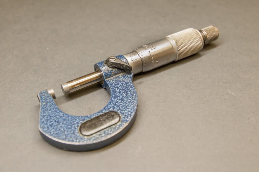
Learning how to use a micrometer is an essential skill for a machinist.
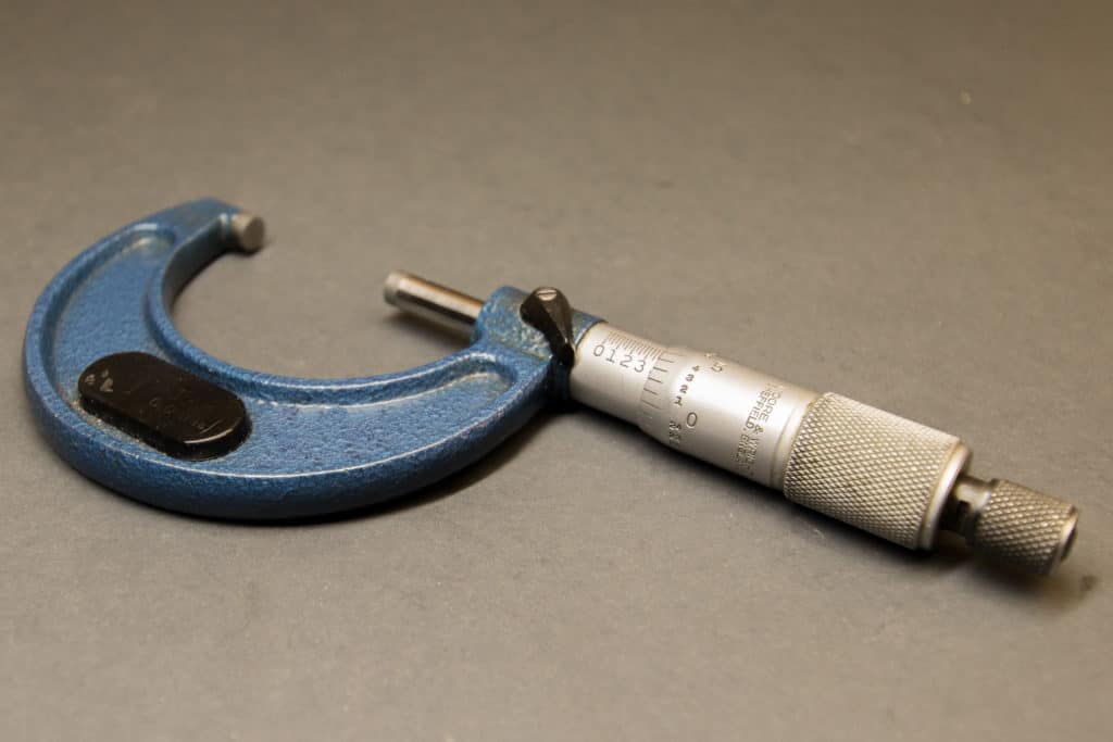
Outside micrometers are designed to measure the outer size of an object, whether it is a round bar or a square block.
It can only measure parallel or convex circular faces.
It measures using a spindle attached to an accurately calibrated screw which you wind until the part to be measured is gently clamped between the fixed anvil and the spindle.
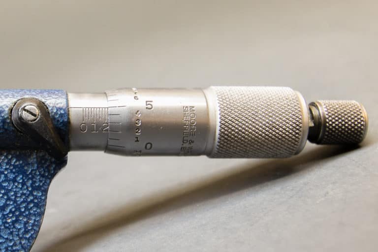
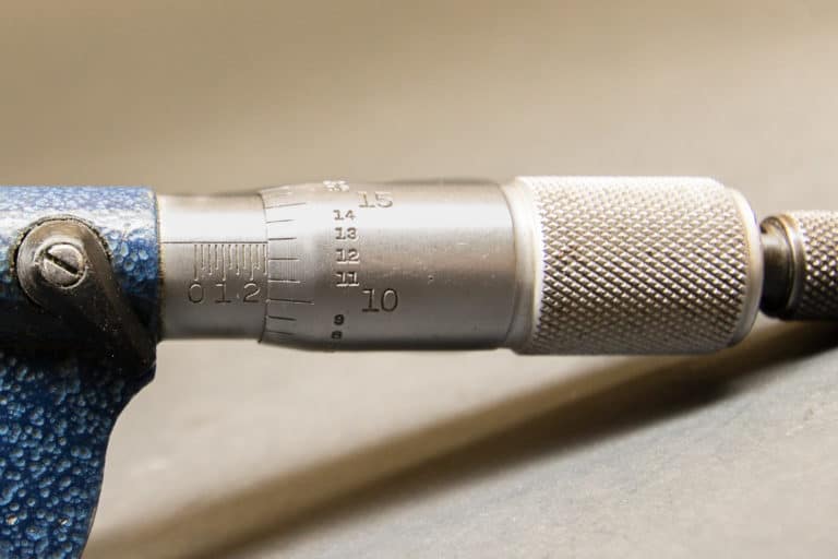
You then read the position of the spindle along the thread using a scale on the outer diameter. This is a lot easier to show than explain. So here’s a picture.
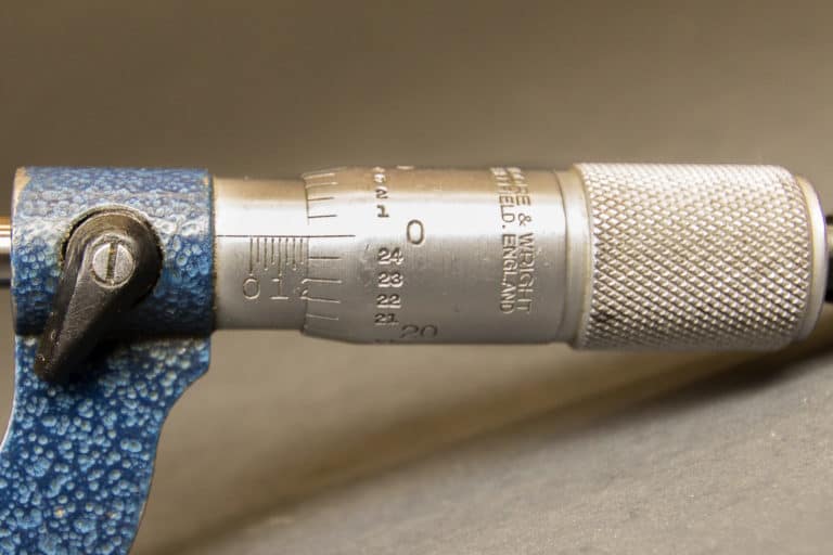
Not all micrometers are made equally, some being more accurate than others and can be provided with calibration certificates. There are less expensive generic micrometers that will probably be good enough for home use.
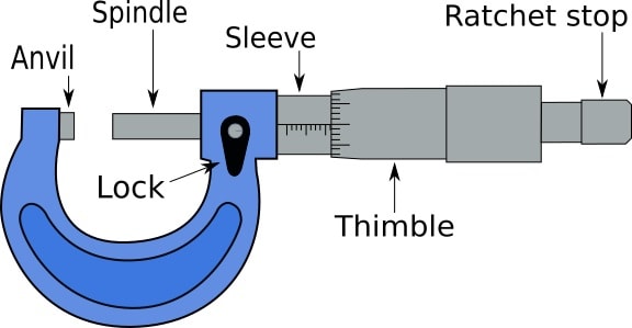
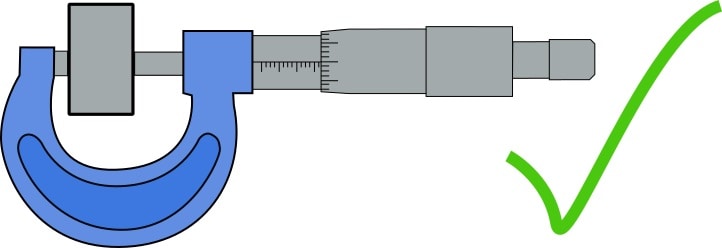
Measuring with a micrometer consists of gently “clamping” the part to be measured between the anvil and the spindle. The spindle is wound in until you are close to the part, then you can use the ratchet stop.
The ratchet stop prevents you from over tightening the spindle against the part. It will click and spin when it meets resistance.
To make sure you are correctly against the part you can carefully wiggle the micrometer while turning the ratchet stop.
This helps to ensure the anvil and spindle are sat square against the part. Just keep turning the ratchet stop until the thimble no longer turns.
When you have the micrometer tightened on the part you can read the scale on the sleeve and thimble to get your size. This is done by locking the spindle with the lock lever and gently sliding the micrometer off the part.


The thread size on an imperial micrometer is 40 threads per inch, this means the spindle will move .025” for every revolution.
Each 0.1” on the sleeve scale is divided into 4 seperate divisions of .025”.
So every full revolution of the thimble will move to the adjacent marker on the sleeve.
This dictates that the scale around the thimble has 25 increments of .001” covering the complete circumference.

To obtain the size, you read the division on the sleeve where the edge of the thimble is.
For example, if the edge of the thimble is between 0.2 and 0.3 on the sleeve, it will be 0.2 plus the amount of .025” divisions, plus the number on the thimble scale.
I found this link to a virtual micrometer which you can practice with.
If you are considering buying your own micrometers for your home workshop, I have written an article ‘Best Micrometers‘ which will help you choose which is the best for you.
Digital calipers
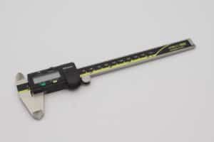
Digital calipers are probably the most versatile measuring tool you can buy. They are not the most accurate but machinists use them the most for general lower tolerance measuring.
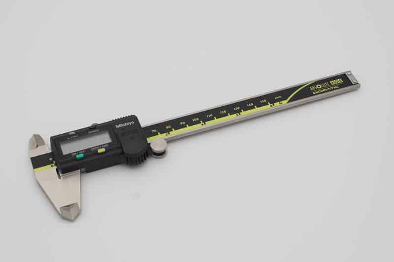
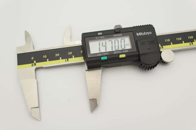
They have a large measuring range compared to micrometers and can be used for inside dimensions and depths as well as outer sizes. They consist of a fixed jaw on one end and a sliding jaw with a digital readout.

Slide the moving jaw against the part to be measured trapping it against the fixed jaw.
The readout will give you the size in inches or millimeters.
Measuring with digital calipers is very simple. All you do is slide the moving jaw against the part to be measured and the fixed jaw.
The distance will be displayed on the LCD readout. Internal distances can be measured with the internal jaws and depths with the depth blade.


It is important to make sure you are holding the calipers perpendicular or parallel to the part being measured to ensure the reading is accurate.
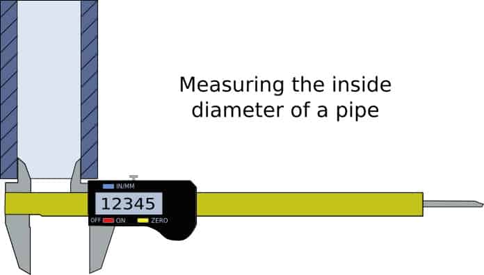
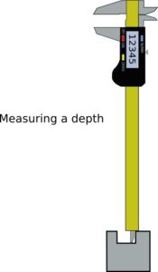
Incremental distances can be measured by using the “zero” button.
For example, a bar diameter can be measured and the readout zeroed. Then another bar diameter can be measured and the calipers will show you the size difference between the two bars.
If you are considering getting your own calipers you can check out my digital caliper buying guide.
Vernier calipers
Vernier calipers are the predecessor to the digital caliper. Instead of using a digital readout they use a vernier scale. Despite being an old design they are still quite common. I have a 14” set in my toolbox that get used occasionally.
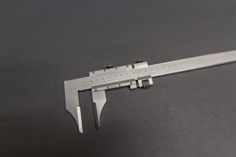
Unlike a digital caliper they are pretty much indestructible, just don’t throw them around and they will last you a lifetime. I’ve had mine nearly thirty years.
The downsides are they are slightly less accurate than digital calipers and the scale gets difficult to read as your eyesight gets old…
Reading a vernier scale is straightforward.
You use the calipers like you would use digital calipers. Making sure they are straight and perpendicular to the faces being measured ensures you will get an accurate reading.
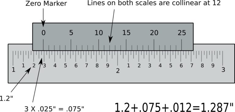
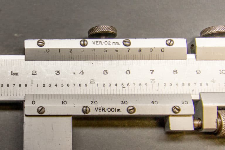
To read your measurement you locate the zero marker on the vernier scale and read off the biggest whole number just behind the zero marker.
Then count the amount of smaller increment markers behind the zero marker, add these up.
Finally, add the number that lines up with a marker on the vernier scale to one on the main scale, (collinear lines). This final number represents thousands of an inch.
For example if the lines are collinear with the number 8 on the vernier scale, add .008” to the total.
The vernier scale can be in .025” increments or .050” increments. If it is in .025” increments this will be reflected on the main scale with 4 marker sections between each .1” increment and with just 2 marker sections between each .100” section with a .050” scale.

You can see in the picture above, these calipers have only 2 marker sections between the .100” markers.
This caliper has .050” increments, you can see that the vernier scale has numbers up to 50 and not 25 as in the previous graphic demonstration.
Depth micrometer
These are a different type of micrometer consisting of a flat base and an interchangeable rod.
They use the same calibrated screw and scale as outside micrometers but are designed to measure a depth.
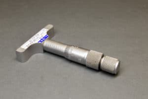
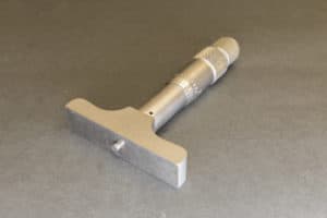
The interchangeable rod means one depth micrometer can be used to measure a large range of sizes, again in 1” or 25mm increments.
To use a depth mic you sit the flat base over the depth to be measured and wind down the thimble until the spindle touches the face you are measuring.
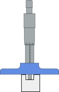
They are read in the same way as an outside micrometer.
Telescoping gauges
A telescoping gauge is used to measure the size of a circular hole. They do not have any scale or ability to show you the size of the hole measured.
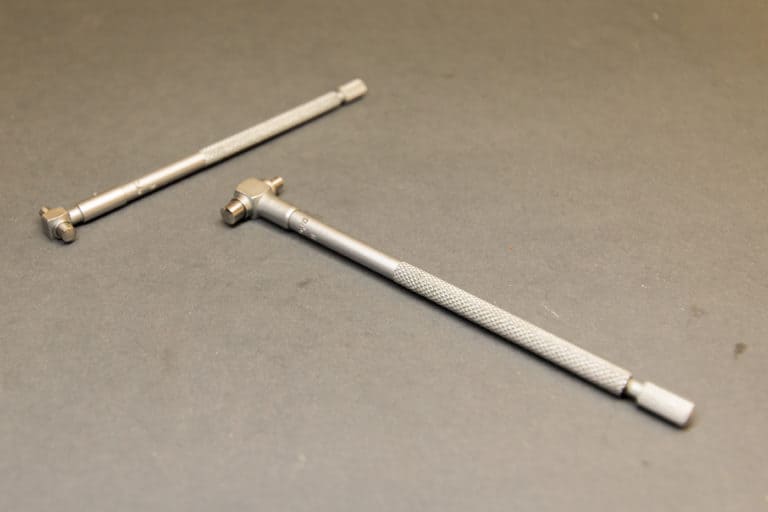
All you use them for is to transfer the size of the hole to the telescoping gauge which can then be measured with a micrometer.
They consist of two opposing plungers being pushed apart by a spring. These two plungers can be locked in place.
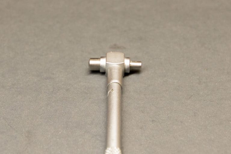
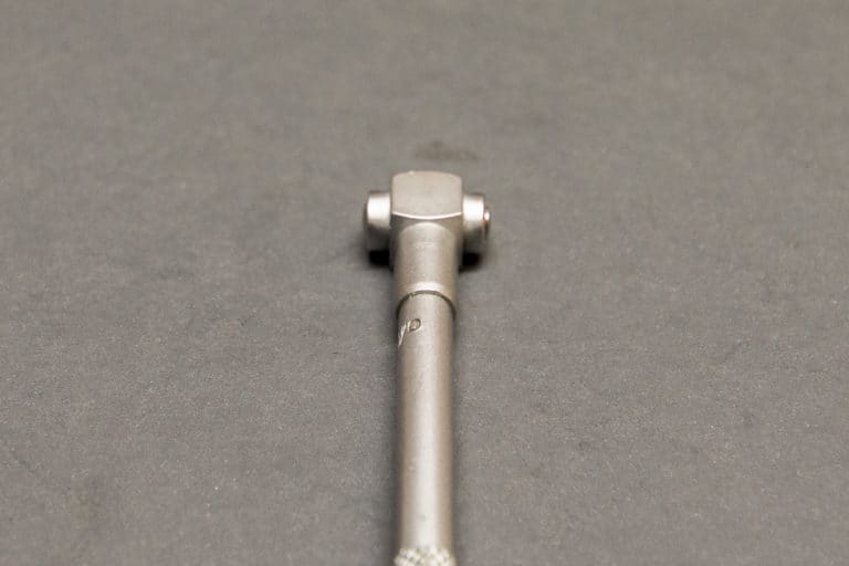
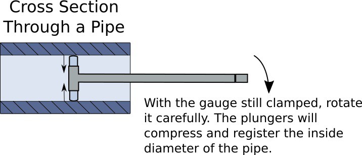
To use them you squeeze the two plungers together and lock them, insert it into the hole to be measured, hold it at an angle and release the lock. When the plungers spring out and hit the inside of the hole, gently lock them in place.

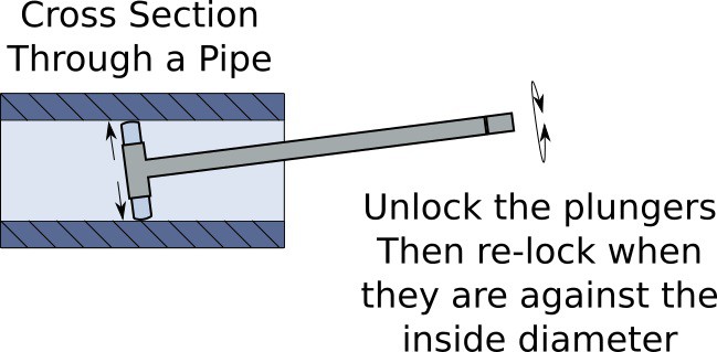
Now, when you roll the gauge straight, the plungers will slide against the hole walls slowly compressing in, which will register the width of the hole.
The gentle lock you applied allows the plungers to slide together under the rotational force, but prevent them from springing back open.
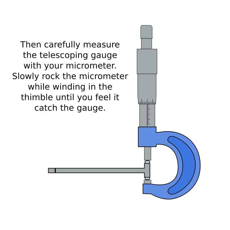
Now you can gently measure the gauge with a micrometer to size the hole being careful not to squeeze the plungers in..
If you are looking to purchase a set of Telescoping gauges, I recommend this set from Starret. It consists of 4 smaller gauges making it an ideal set for the size of parts that a hobby mill can handle.
Starrett are an American company and produce some of the best tools available for machinists.
They are quite expensive but they will work well and last for a lifetime if they are looked after properly.
- Best Performance - The Starrett Telescoping Gage is the perfect tool for determining the true size of holes, slots, and recesses. This tool will become an indispensable tool in your arsenal.
- Precision Ground Radius - Each gage is precision ground with a radius, providing two-point contact for maximum accuracy. This guarantees that the measurement you take is precise and consistent every time.
- Durable Construction - The telescoping gage is made from highest quality material ensuring that it will last through even the most rigorous use. It can handle any job you throw at it, making it a versatile tool for your workshop.
- Reliable - Featuring a handle with one rigid contact arm and one spring-tensioned telescoping contact arm which ends of both contacts are hardened and ground to a radius to allow proper clearance on the smallest hole the gage will enter.
- The Standard for Excellence - Manufacturing quality tools that provide consistent and reliable performance since 1880, Starrett's commitment to product excellence, has earned them a reputation as one of the most trusted names in the industry.
Ball Gauges
For smaller holes you can use a ball gauge, these work by spreading a “split ball”.
They are used in the same way as a telescoping gauge, but the design allows a smaller diameter to be measured.
You put the gauge inside the hole and gradually open it up while rocking it back and forth until you feel it touch the inside of the hole. This can then measured with a micrometer. You can use these on holes from about ⅛” up to about ½”.
- Measures Accurately - The Small Hole Gages are ideal for accurately measuring small holes, slots, grooves, and recesses. This makes it perfect for general work where more accurate measurement is required.
- Safe and Smooth Adjustment - It is designed with a smooth and sensitive adjustment that makes it easy to get the perfect fit. The adjustment range is also restricted by a safety stop, preventing breakage and damage.
- Best Performance - These gages have a precision ground radius on each gage that provides two-point contact for maximum accuracy and a hardened-ball measuring the surface with two-point contact.
- Ergonomic Design - Manufactured from high-quality material to provide dependable service in the field or shop. It is designed to be convenient and well balanced to ensure stability when used.
- The Standard for Excellence - Proudly made in the USA, Starrett combines over 140 years of American heritage and innovation with globally sourced materials to deliver exceptional quality tools and products.
Just like the telescoping gauges I’m going to recommend a quality set over the budget products.
These starrett hole gauges will be perfect to last a lifetime when used with care, which in my opinion justifies the extra cost.
Pin Gauges
For even smaller holes you can use pin gauges. These are accurately ground pins and come in sets.
All you do with these is find the pin that just slides into the hole, i.e. the biggest one that will fit. That will be the size of your hole.
- [Durable and Reliable]: Our pin gauges are made of bearing steel, heat-treated to a hardness of 60-62 RC for durability and long-lasting reliability.
- [Complete Set]: This 190-piece kit covers a range from 0.061 to 0.250" with a minus tolerance of 0.0002" and a step of 0.001". Each length is 2"±0.01".
- [Enhanced Features]: The gauge surface is polished and burr-free, with a finish of 10 microns or better.
- [Clear Markings]: Comes with a storage case to keep the pin gages organized. Each gage size is clearly marked in the case, and size information is etched on each pin gage making it easy to identify and use.
- [Versatile Use]: Great for checking diameters of holes, bushings, and worn parts, as well as the distance between holes and hole location. It can also calibrate vernier calipers, micrometers, and other measuring equipment to detect geometric deviations.
This set pictured above is a from HFS and is available on Amazon. I am recommending them because they are affordable and also they are a ‘minus’ specification.
The ‘minus’ specification means they are ground a couple of tenths (.0002″) smaller than the recorded size.
This enables the pin to slide in the hole that you are measuring. For example, if you try and slide a .250″ pin into a hole exactly .250″ diameter it will not go, it will be an interference fit.
But because the ‘minus’ .250″ pin is actually .2498″, it should just about slide in the hole. This allows a .250″ pin to size a .250″ hole.
Dial test indicator
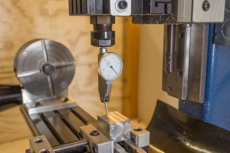
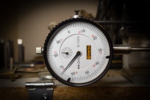
Dial test indicators are used primarily for checking for flatness of a part or how square it is. For example it can be used to get your vise square on your Cnc machine.
They can also be used for many other uses such as measuring depths and distances when used on a machine or with it mounted on a magnetic stand.
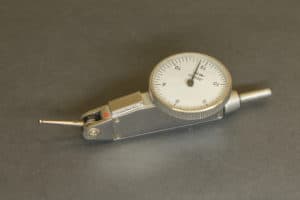
A smaller finger dial indicator is more useful for a desktop cnc machine. They can be used directly in the spindle to dial in a part and find its X and Y datum positions.
