G codes and M codes
The terminology you will encounter when you are researching cnc machining can be confusing, knowing what they mean will be a good start to your Cnc education.
The most common type of terminology you will encounter will be G code and M code commands. These are just prefix letters for writing G code programs which the software running your machine can use to execute various commands.
There are lots of these commands, but for hobby machines you will only need to get familiar with a small handful of each type.
I have listed the most common here:
G codes
- G00 = rapid movement
- G01 = move at the specified feedrate
- G02 = clockwise arc or circle movement
- G03 = counter clockwise arc or circle movement
- G17 = X Y plane selection
- G20 = coordinates in inches
- G21 = coordinates in MM
- G28 = home position return
- G40 = cutter compensation cancel
- G41 = cutter compensation left
- G42 = cutter compensation right
- G43 = tool length compensation on
- G53 = cancel work offsets
- G54,G55,G56,G57,G58 and G59 = work offsets
- G80 = cancel canned cycle
- G81 = basic drilling canned cycle
- G83 = peck drilling canned cycle
- G90 = absolute programming
- G91 = incremental programming
M codes
- M00 = program stop
- M01 = optional stop
- M03 = spindle on
- M05 = spindle off
- M06 = tool change
- M30 = end of program, rewind and reset
This list may seem like a lot to learn but quite a few of these codes will only be used once in each program you do. The most frequently used codes in a program will be G00, G01, G02 and G03 movement commands, depending on how complex the tool path is.
General Cnc Terminology
I’ve listed some of the most common terminology below, although I could have ended up with a huge list I considered the most likely ones a hobby cnc user might come across.
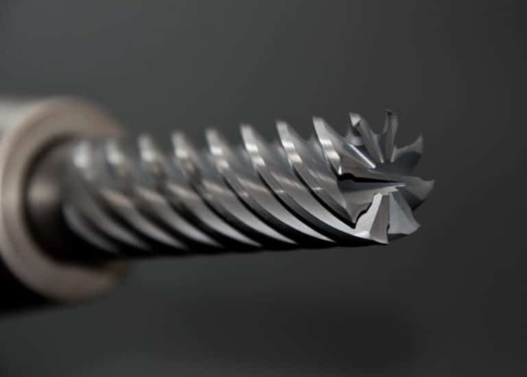
Endmill
Endmill is a general term used to identify a milling cutter. Specifically one that uses its edge to do the machining. Although most newer (modern?) carbide endmills are capable of cutting on both the face and the edge. This means the tool is able to plunge, i.e. drill into the workpiece.
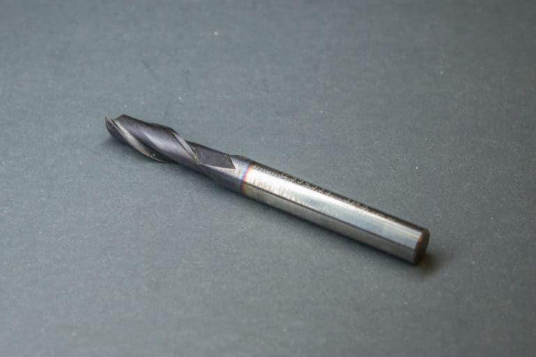
Slot drill
A slot drill is just a 2 flute endmill and as such it is more able to plunge faster enabling it to be the tool of choice for machining slots. The extra clearance with only having 2 flutes leaves more room for the chips to evacuate helping to prevent the tool from clogging up and breaking.
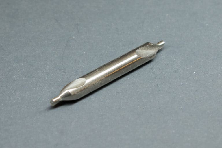
Center drill
A center drill is a short and sturdy tool that is used to create a hole for a lathe center. It has two diameters, the smaller diameter prevents the lathe center point from bottoming out in the hole. It can also be used for creating a guide hole for a HSS drill. The hole it creates is used to guide a HSS drill bit so that it does not wander when it starts to drill into the part.
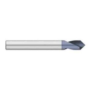
Spot Drill
A spot drill is similar to a center drill but its only purpose is to create a positioning guide for a HSS drill. It can also be used to chamfer small holes. To program a spot drill you would use a G81 canned cycle, e.g. G81 R.1 Z-.02 F2.
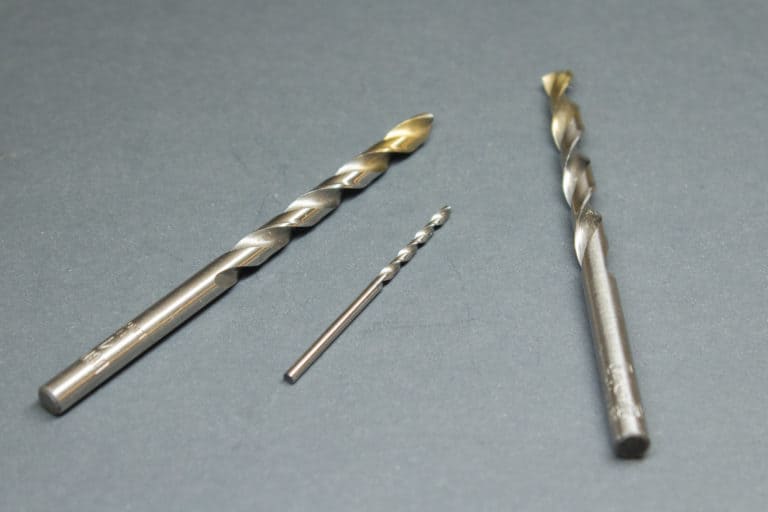
Drill Bit
A drill bit is a tool for drilling holes. They can be used in a program with a G83 canned cycle.
e.g. G83 R.1 Q.05 Z-.5 F2.5
Thread Mill
A thread mill is used for thread milling to create internal or external threads using a cnc milling machine.
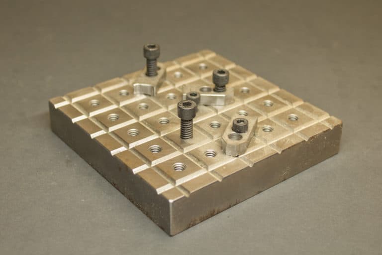
Fixture Plate
A fixture plate is an additional plate that can be clamped to a milling machine table with customised clamping features for a specific type of milling operation.
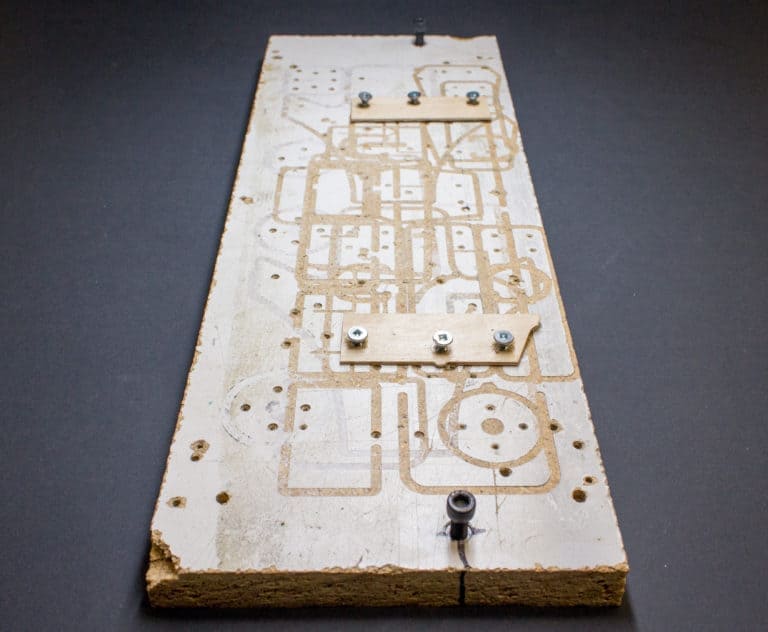
I even have a fixture plate made from melamine board. This is useful for machining wood or plastic with the board being a sacrificial piece. This means a profile can be machined deeper than the part without damaging the actual table of the machine.
Spindle speed
This is the r.p.m of the machine spindle. It is specified in a g code program with an S.
E.g. S1200 M03
Most desktop cnc mills will not have the ability to automatically change the spindle speed but it will still be posted in a program if you use CAM software. It will not produce an error if your spindle is not controlled by the software, the command will just be ignored.
Feed Rate
This is the speed the machine will move the tool at. The feed rate is stated in the program and can be changed on every new line of code.
The g code prefix is an F, e.g. G01 X2. Y0. F30.
The unit of feed is inches per minute for imperial programs and millimeters per minute for metric programs. It dictates how far the machine will move the tool per minute, e.g. F30. in an imperial program will move the tool 30 inches every minute.
See my feeds and speeds article for an in depth look at working out feed rates.
IPM
This is an acronym for Inches Per Minute for describing a feed rate. See above.
IPR
This is an acronym for Inches Per Revolution for describing a feed rate. This type of feed rate will be very small, e.g. a feed rate of F.012 would be typical for an endmill. So in this example the tool would move .012” for every revolution. The equivalent feed rate in IPM would be 24 if the spindle speed was 2000 RPM.
2000 X .012 = 24
IPT
This is an acronym for Inches Per Tooth for describing feed rate (also known as feed per tooth). This is similar to Inches Per rev but enables you to differentiate your speed rate based on how many flutes the cutter has. For example an IPT of .003” with a 4 flute cutter turning at 2000 RPM will have a feed rate of 24” per minute.
.003 X 4 X 2000 = 24
Safety Plane
This is a Z axis height at which it is safe to use rapid movement. The height of this is set by the programmer and will usually be determined by how high any clamps or fixturing are in the work area.
Datum
A datum is a fixed position on your workpiece which is set as the active work offset with the X, Y and Z axes at zero. E.g. G54 offset position.
Machine Reference position
Also known as a machines home position. This is the position where all axes on the machine are at zero with no work offset active.
MDI
MDI is an acronym for Manual Data Input. This is a mode in your cnc control software that lets you input and execute single lines of code. This is useful for doing simple operations that may usually be done on a manual machine.
Offset Page
This is a page on your cnc control software that displays your offset tables. It will show your datum offset values for each stored offset, G54, G55 etc and your tool length offsets for each tool, e.g. T1, T2, T3, etc. The offset page will also show the Diameter or radius offsets for each tool.
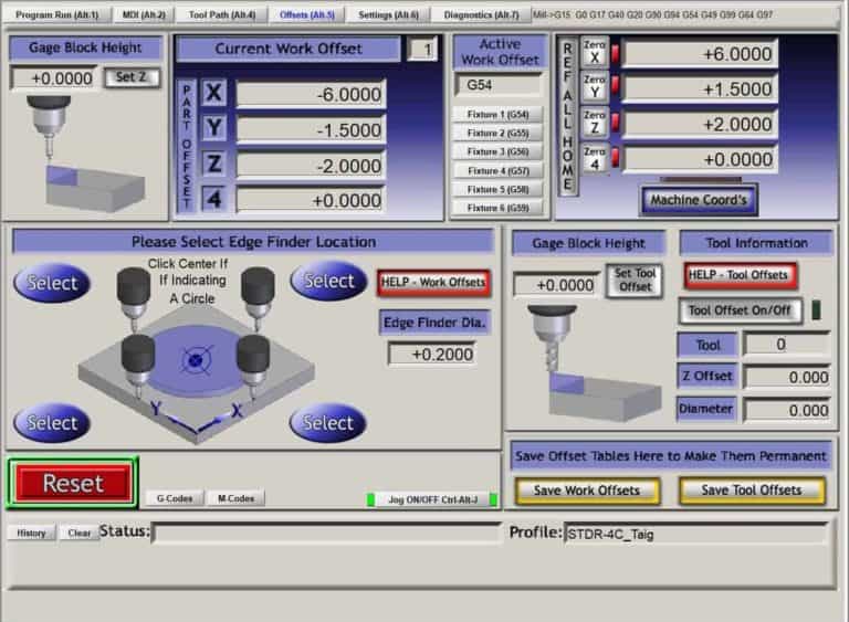
Work Offsets
Work offsets are stored values for G54 to G59. They consist of distance values for each axis from the machines reference position.
Tool Offsets
Tool offsets are stored values for the length of the tool and also the radius or diameter offset values.
Climb milling
Climb milling refers to the direction an endmill is moving in relation to the side of the tool that is cutting the material. When a tool is climb milling it is behaving like a rolling wheel. This can also be described as “cutter left”. The G code for cutter compensation left is G41. An example line of code would be G01 G41 D1 X2.1 Y0. F20.
Conventional Milling
Conventional milling is the opposite of climb milling. It is when the endmill’s direction of rotation is turning against the direction of travel. Also known as cutter right. The G code for cutter compensation right is G42. An example line of code would be G01 G42 D1 X2.1 Y0. F20.
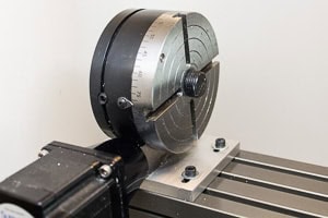
4th Axis
4th axis refers to the addition of an extra axis to the cnc machine after the 3 main permanent axes, X, Y and Z. A 4th axis is usually rotary and will be clamped to the table on any side.
It doesn’t spin like a lathe chuck, but is powered by a stepper motor so it can programmed to move measured amounts just like any of the main machine axes.
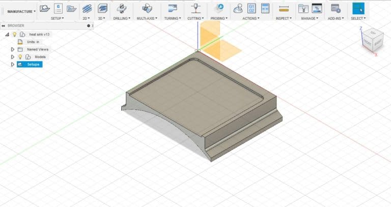
CAD/CAM
Cad is an acronym for computer aided design, Cam is an acronym for computer aided manufacturing. These can be separate software programs or combined. Cad is used to design or draw the part to be machined, and Cam is used to create the cutter paths and also post process the cutter paths into a G code program.
Post Processor
A post processor is normally integrated into CAM software, it processes cutter paths into G Code programs.
Absolute programming
The machines positioning is always referenced from the active part datum. G90 is the G code that commands Absolute programming mode.
Incremental programming
The machines positioning is always referenced from its previous position. G91 is the G code that commands incremental programming mode.
Thou
“Thou” is short for thousandth. It refers to one thousandth of an inch, or .001”.
Tenth
“Tenth” refers to a tenth of a thousandth of an inch, or .0001”.
Chatter
Chatter is a descriptive term used when a workpiece is vibrating and the tool leaves a rough or uneven finish on the machined surface.
Push off
This is another descriptive term that refers to the effect of tool deflection. Commonly seen when using a long endmill that deflects from the cutting forces applied to it. The result is a vertical face that’s not so vertical. The amount of deflection is usually only a few “thou”.


