What are G code G54 cnc datums?
Datums can also be referred to as machine offsets or Work Coordinate System (WCS) positions.
Every time you use a cnc machine it needs to know where the part is located. You tell the machine where the part is by using datums. All you do is set the distance to the part from the machine reference (home) position.
You will need to decide where on the part you want your datum before you create your Gcode program.
Then, when you set up the machine to run the program you will position the datum on the raw stock in the same location as the program.
This could be a corner, if the stock material is a square machined block. Or if you have a rough sawn block of metal with no defined edges, you could locate the center of the part, then move to where the corner of the part will be when it is finished.
How to set the part datums on a cnc machine
On a typical hobby cnc machine there will be three axes, X, Y and Z. So you will need to set all three axes everytime you setup a new part in your machine.
The X and Y axes will be set using the same method but the Z axis will be set in a slightly different way.
Locating the X and Y datums using a cnc edge finder
The most common tool for a hobbyist to set the X and Y datums is a cnc edge finder. There are different variations of edge finder design but they all operate the same way.
The end of the edge finder has a separate part that is held with a spring. Move the end so it is slightly offset. It will now wobble when it is rotated. Load the edge finder in the spindle and start the spindle.
I typically have the rpm set quite low, about 1000 rpm.
Then manually jog the part close to the edge you want to set. When you get close, reduce the increments so the axis only moves very slowly. The end of the edge finder is moved against the edge of the part until it stops wobbling. It will then move to one side when it reaches the edge of the part.
Note: Using an MPG Pendant to jog your machine is the easist way to use an edgefinder.
Now the spindle is located accurately against the side of the part you can go ahead and store the position using your machine control software. It will be stored in the work offset table. You will have to choose the offset number you used in your Gcode program.
After you have stored the offset it will need adjusting to compensate for the radius of the edge finder. In my case the edge finder end is 0.2″ diameter, so I will change my stored offset by 0.1″.
This will put the stored datum value exactly on the edge of your part.
You can now repeat this process for the other axis. Once you have set your X and Y datums you can set your Z axis.
Setting the z axis datum
The way you set the Z datum on a hobby cnc machine is different to how it is set on an industrial cnc machine. Almost all industrial cnc machining centers have a tool changer with a magazine full of tools at the operators disposal.
A typical hobby machine does not have this option.
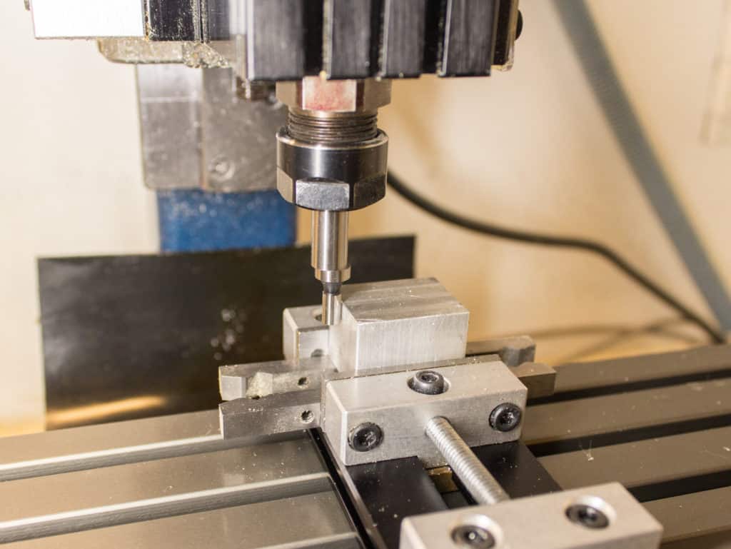
The simplest and best way is to tighten a tool in the spindle and manually touch it off onto the face of the part you have chosen as your Z datum.
All you do is jog the tool down slowly onto the top of the part, without it spinning.
Do this in the same way as setting your X and Y datums with the edge finder.
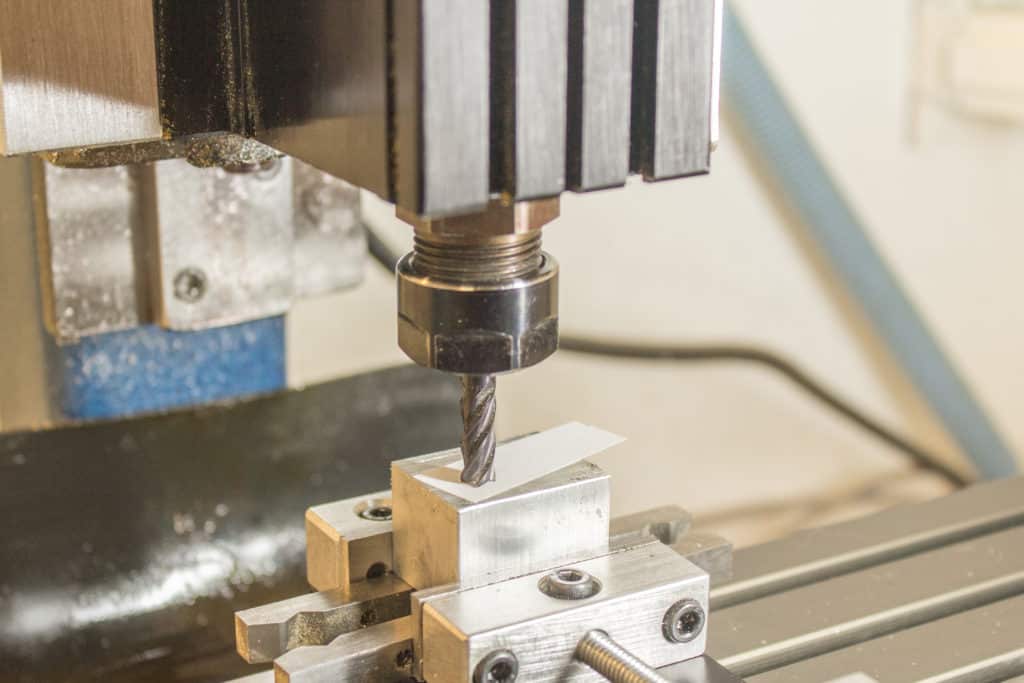
When you get close, but still maintaining visual separation, slide a feeler gauge between the tool and the face.
A piece of paper can be used as a feeler gauge.
Move the tool down in Z using .001” (.0254mm) increments.
As soon as the cutter bites into the feeler gauge you will know how far off the tool is to the face. You can now store this position in the Z value field of your offset page.
You will have to repeat this process every time you load a new tool for milling your part, because it will be very unlikely that you will be able to machine a project with just one tool.
One important point to note with this method is that you are ignoring the use of a tool length offset. These are really only useful when you have a tool changer and a tool magazine full of tools. Just check that the tool offset number you are using is set to zero.
What are the Gcodes for cnc datums?
The most used Gcodes for datum positions are:-
- G54
- G55
- G56
- G57
- G58
- G59
There are different variations depending on the machine and its software but these codes are the most common.
Using these means you can use all six of these offsets at any time and even in the same program.

This would be useful if you had a fixture that held six identical parts, you could write one program then copy and paste it six times using a different offset code, each offset code being set to a different part position.
G53 is the Gcode that cancels any currently active offset code.
When there are no active offset codes the machine will use its machine zero (machine reference or home position) instead of the part zero (G54 through G59).
It is not recommended to set your machine zero (home position) at the part datum, you need to recognise the difference between the two and understand how they relate to each other.
Don’t have an edge finder or wobbler?
If you don’t have an edge finder of any kind there are alternative ways of setting your X and Y datums.
The simplest way is to use a dowel or turn a cutter upside down in the spindle. All you do is jog the dowel carefully towards the edge of the part. Then you place a piece of paper or feeler gauge between the dowel and the part until the dowel grips the paper or feeler gauge.

You can then set the position taking into account the radius of the dowel (or cutter) and the thickness of the paper. This is a similar method to how I described setting your Z offset.
If you own a small finger dial you can hold it in the spindle and “sweep” the side of the part.
This involves rotating the spindle by hand so the high point of the arc hits the zero on the dial.
Then note the machine position value and move the dial to the other side of the part and repeat.

You now have two values for that axis. All you do is add them together, divide the result by 2 and the answer will give you the middle of the part. Manually type this value into the offset table.
If you use a vise for making a part you can find the position of the fixed jaw. Everytime you grip a part in the vise you will know the Y axis datum, or at least be able to calculate it from the fixed jaws known position.


