SVG to G Code
One of the hardest and most frustrating challenges for a new cnc hobbyist is converting an SVG to G Code for your own cnc projects. Just learning what processes you need to go through to get to a finished project can be a lot to take in at first.
If you can relate to this problem, just keep reading this article, it will help you get started.
I will show the process of using a free G code converter which uses SVG files. This will create any basic 2D shapes for your cnc router or mill.
The examples in this article will be aimed at basic cnc machines like the 3018 engraver, as this is the type of cnc router that people start with in this hobby.
Follow the link for a complete 3018 unboxing review and setup tutorial of this type of machine on this website.
Free SVG files
One of the best file formats to create free cnc patterns for your projects are SVG files.
SVG stands for ‘scalable vector graphics’, a full explanation can be found on wikipedia.
To create your own SVG files you need SVG software. Inkscape is a high quality downloadable software that fills this need perfectly.
Inkscape does include an addon extension that can create G Code but it is really clumsy and unreliable and I do not recommend it.
JSCut
To avoid having to use inkscape’s useless g code generator extension you can use JSCut.

This is a browser based software program for generating G Code from SVG files, specifically Inkscape.
Creating SVG Files
SVG files are available on the web, some for free, some paid, but the best SVG files are the ones you create yourself.
This will mean you have to learn how to use Inkscape.
Inkscape is a very complete piece of software and a full tutorial would be too lengthy for this article. There are many comprehensive tutorials available, Udemy is a good resource.
I recommend checking out the Udemy comprehensive beginners course, click the link below to learn more.
Prepare your SVG file for JSCut
I will explain here what you need to do in Inkscape to make your SVG files usable for JSCut and a cnc machine.
- Open a new Inkscape document
- Open document properties
- Change the display units to mm or inches
- Change the custom size to the same units
- Change the custom size to match your machines table size
- Change the scale value to 1.000
- Create a shape that matches the size of the blank material you are using
- Use the dimension boxes in the ribbon bar to create accurate sizes
- If you create a shape, make sure to remove the fill color so it just has an outline
- Adjust the stroke width and remove fill color using, Object => fill and stroke
- Change the object to a path
- To do this you select the object, => Path => Object to path


Once you have your blank material size established you will be free to do whatever design you want inside the boundary of your material.

Simply save your finished Inkscape creation and you will be able to load it into JSCut.
Download SVG Files
Another option is to download an SVG file, open it in Inkscape and resize it to fit inside the boundary of your blank material. Once you have resized it, convert ‘object to path’ and save it with a new name so you don’t overwrite the original.
This can then be loaded into JSCut.
JSCut Tutorial
JSCut has been designed to convert SVG files from Inkscape, to g code.
Even though it is far superior than the g code extension that is bundled with Inkscape, it still only has basic CAM capabilities.

With this in mind, you sometimes have to ‘trick’ the software to do what you want.
Testing and trying different operations until you are satisfied with the result is a typical process you will have to follow.
JSCut Settings
When you open JSCut in your browser, it loads with its default settings.
JSCut will allow you to change these settings and to save your changes so you can load them when needed.
One of JSCut’s shortcomings is that only one tool can be used for your loaded SVG file. So it makes sense to save multiple setting files for all the different sizes of tools you own.
This means you can quickly change all the settings to match the feeds and depths of cut etc, for all the different tools you own.
To save each setting just make your changes and click ‘save settings’. A box will appear with the file name ‘settings.jscut’.
Just change the word ‘settings’ to your new name, e.g. metric3mm.jscut, which could represent metric units and a 3mm endmill.

You then have a choice of where to save your settings. They can be saved to your PC or your browser, I typically just save mine to the browser.
To load your settings click the ‘open settings’ drop down menu and choose the relevant option. If you select ‘in browser’ a box will appear with another drop down menu where all your saved settings will appear.

Operations
This option box allows you to set your pixels per inch. It should load as 96 by default as this is what Inkscape uses. If you use different software you may need to change this to get accurate sizes for your G Code.

Create Operation
The create operation option is for choosing your machining strategy.

The options are;
The pocket option will machine an area inside your selected profile. This can be combined with other profile selections inside a larger area. I will show this in my demonstration later in this article.
Inside
This will machine your chosen profile offsetting the tool to the inside. There are further options with the drop down menu. Such as climb or conventional milling directions.
Outside
This will machine your chosen profile offsetting the tool to the outside. There are further options with the drop down menu. Such as climb or conventional milling directions.
Engrave
This will trace your selected profile. Depending on the width of the profile ‘stroke’ and the type and size of cutter, it can trace along the center or on both the outside and inside of the stroke.
This is something you have to test and try different options to get the result you want.
V Pocket
This option will only work if you have specified a vee shaped or angled cutter. It will create a vee groove to the width of your selected line or profile. This is another option you have to test, it can produce some odd results depending on the profile.
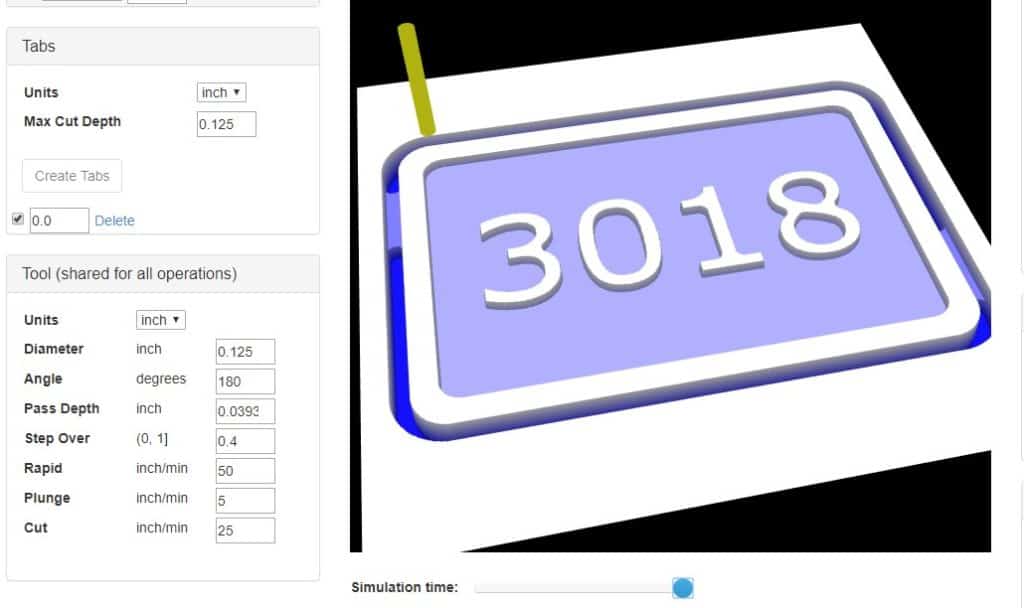
Tabs
Use this to create tabs to hold your part to the stock if you are milling an outside profile. I will explain how to do these in my example later in this article.

Tool
This is where you set all the options for your tool size, depth of cut etc

Diameter
Type in the diameter of the cutter you are using.
Angle
The angle refers to the taper of your cutter.
For example the cutters supplied with the 3018 engraving machine have a 20 degree angle, so you would type in 40 for this tool. The 40 refers to the inclusive angle.
A 45 degree chamfer tool will have a 90 degree inclusive angle.
Pass Depth
This refers to the depth of cut you want to use for the tool.
For example, if you are cutting 1mm deep and you want a 0.5mm pass depth, the tool will complete two passes to get to the required depth.
Step Over
This option lets you set what percentage of the tool’s diameter you want to overlap when milling out a pocket or a large flat area. Your value will be between 0.1 and 1, 1 being 100% of the diameter and 0.1 being 10%.
Rapid
This option lets you set the rapid feed value. The rapid feed is used when the G00 code is utilised for when the tool is not cutting the material.
For the 3018 cnc machine I set this for around 1200 mm/minute or 50 inches/minute.
Plunge
This is the feedrate that the tool will move at when moving along the Z axis, when ‘plunging’ into the material.
Cut
Cut refers to the feedrate at which the program will run when the tool is cutting the material.
Material
This option box lets you set various options related to the Z axis movement.

Make all mm
Clicking on this text will change all the units in every option box and the text will be underlined while this is active.
Make all inch
Clicking this will toggle to make all units inches and this will be underlined instead of ‘make all mm’.
Thickness
You can type in the thickness of your material here, this is only important if you select your Z axis origin at the bottom of your material.
Z Origin
Here you can select where you want your Z axis datum, the top of the material or the bottom. My advice is always choose the top, this software is not advanced enough to produce programs that would benefit from having your Z datum anywhere but the top.
Clearance
This lets you set your clearance height. The distance above the material that the machine will make rapid moves at. This does not have to be high unless you need to avoid clamps.
Curve to line conversion
This option box lets you set your tolerance accuracy.
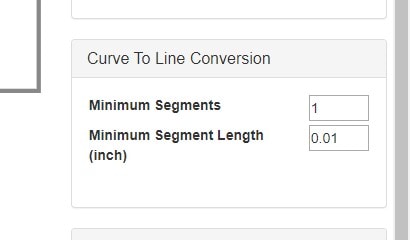
Jscut will convert all arcs and circles to small lines. This will produce facets on the curves but if they are really small you should not see them.
Minimum Segments
This option sets the minimum amount of lines to use for an arc.
Minimum Segment Length
This option can be used to reduce the length of the ‘facets’ in the curves.
Using this will increase the accuracy of the curve, but doing so will increase the size of the G Code program.
Gcode Conversion
This option box allows you to make changes to how the software post processor outputs the G Code.
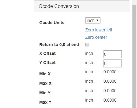
G Code Units
This option allows you to decide which unit of measurement the G Code will output.
You should really keep these the same throughout the whole process.
Zero lower Left
When this is clicked and the text is underlined, the G Code will be output with the X and Y zero datums set at the furthest position of your geometry to the lower left.
Zero Center
When this is clicked it will underline and toggle away from ‘zero lower left’ and the G Code will be output with the X and Y zero datums in the center of geometry.
Return to 0,0 at End
If the box is checked, the G Code will output a final move to the X and Y zero datum position at the end of the program.
X Offset
This value enables you to move your entire G Code program by a set amount along the X axis. This gives you control over where your program will be positioned on your stock material.
Y Offset
This value enables you to move your entire G Code program by a set amount along the Y axis. Use this in conjunction with the X offset.
Creating a simple G Code Program
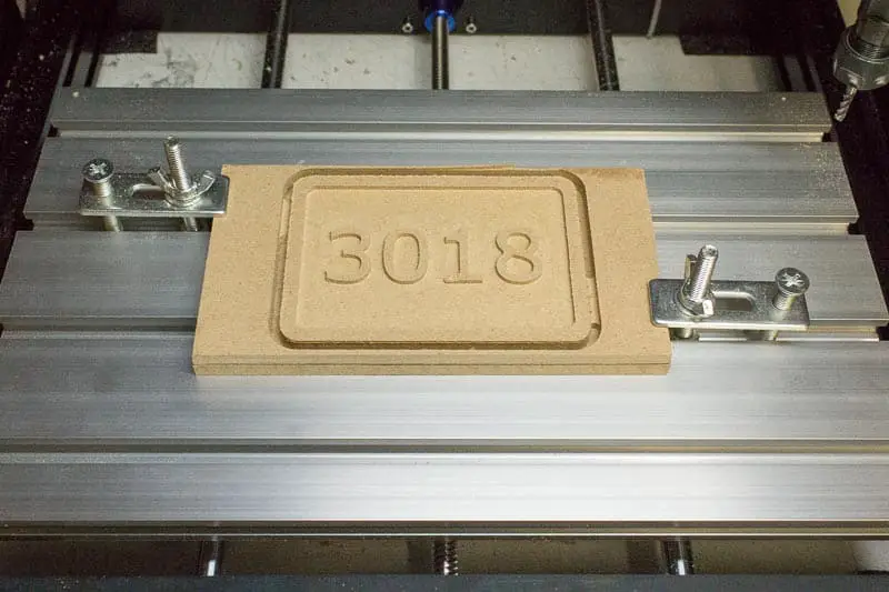
I created a design in Inkscape using the rectangle tool and some text. I made a rectangle that represents the size of the stock I am using and created a double border with some text inside. The outer border rectangle will be cut out of the stock so I need to create holding tabs.
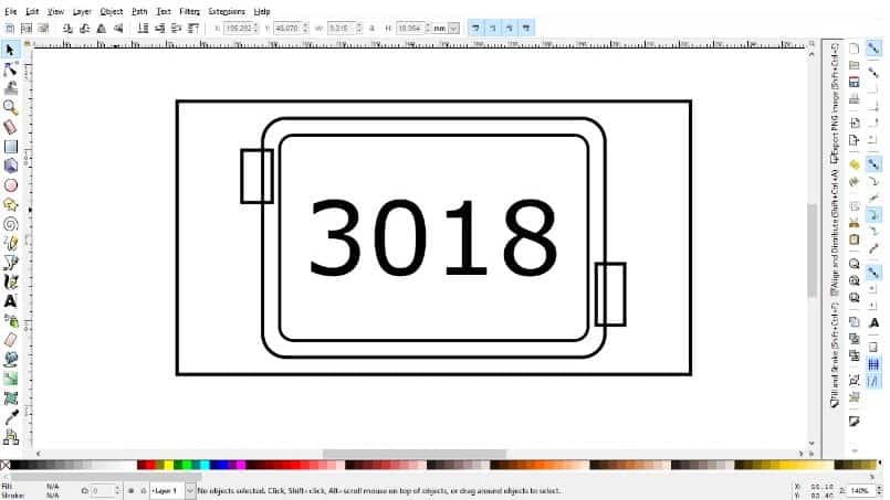
The tabs are created using small rectangles. Any closed shape can be used for this purpose.
- Open JSCut in your browser and select ‘open SVG’ and load your file.
- Load one of your pre-set settings now to match your chosen tool.
Create The machining Operations
Now you can create the tool paths to machine the project.
For this example I am going to machine the lettering first then cut out the profile last.
I am not going to engrave the letters but machine around them, inside the border.

- Use your mouse to select each letter first, then select the inner border.
- Click ‘create operation’
- Select ‘Pocket’ from the drop down menu
- Type in the Z axis depth you want to machine down to
- Click the small black arrow to expand the operation options
- Give the operation a name
- For the combine option select ‘Xor’
- Change the direction to ‘climb’
- Click ‘Generate’
- Your toolpaths should appear


Next you can create the profile pass to machine the outer profile to cut out the part.

- Use your mouse to select the outer profile.
- Click ‘create operation’
- Select ‘Outside’ from the drop down menu
- Type in the Z axis depth you want to machine down to
- Click the small black arrow to expand the operation options
- Give the operation a name
- For the combine option just leave it as is
- Change the direction to ‘climb’
- Click ‘Generate’
- Your toolpath should appear
Create the Tabs
To create the tabs, simply select both of the small rectangles. Then type in the max cut depth box the depth at which you want the tabs to start then click ‘create tabs’.

The tabs should turn red.
Now you can select ‘simulate Gcode’ to have a look at the simulation.
Create the G Code
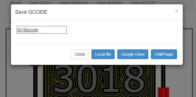
All you have to do now is choose ‘zero lower left’ or ‘zero center’ and click ‘save GCODE’.
Give your file a name and select where you want to save it to.
If you choose ‘local’ it will download the G Code file to your computer.
Running the Program
One issue that JSCut does have is it never seems to add the code to turn on the spindle and turn it off again. This isn’t a big deal but it would be easy for a beginner to miss prior to testing the program.

All you have to add at the beginning to turn on the spindle is M03 S1000 and M05 at the end after the tool has retracted for the last time.

I ran the program on my 3018 cnc engraver that I have reviewed on this website. It was only my second project on this machine and it definitely showed its lack of rigidity.
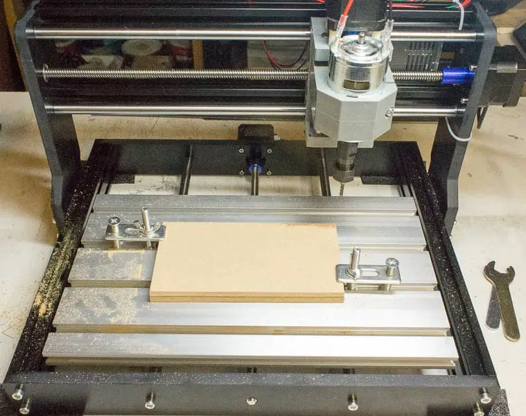
I used particle board for this demonstration and the machine struggled to run at the depth of cut and feedrate I show in this article. I forced it through, but I had to reduce the feedrate to 10 inches per minute (254 mm/min). I really needed to reduce the depth of the cut to about .015” (.38 mm).

Candle Grbl software was used to send the program to the 3018 engraver. I have a full review of Candle on this website.
Universal Gcode sender is another software option for controlling your Cnc machine. Full Universal Gcode sender review here.
JSCut Tips
If you are finding that JSCut is not creating the cutter paths you want, it’s time to be creative. Experiment with different sizes of tools to force the tool path you need.
You don’t have to use the same tool that you specify in the option box, you are just forcing the software to create the path you want.
An example of this is when trying to cnc text engraving. Sometimes it will try and trace the outside and inside of the letters, depending on the size. Switching the tool to a 90 degree angled vee tool, sometimes this works to create a single line tracing the lettering.
Again, testing is key here.
If you need to use different sizes or tool type in the same project you are forced to create seperate programs. This can cause issues with differing datum positions between the two programs.
This can be solved by incorporating the same outer profile in both programs, this will establish the X and Y datums to the same position for both separate programs.
If the outer profile is not needed it can just be deleted from the finished G Code program after it is created.
Conclusion
Using Inkscape is the ideal solution for simple creative projects, JSCut is the best CAM software I have found that converts inkscapes SVG files to G Code.
It isn’t perfect and some testing is needed at times to get the result you are after, but it’s free and the learning curve is short.
These two pieces of software are the ideal solution to get you started creating your own projects.


