GRBL G-Code Commands List
G-code commands, used extensively in the world of CNC machining, play an essential role in controlling the actions of CNC machines. These commands dictate the movements, cutting depths, feed rates, and other intricacies involved in crafting complex designs and structures from various materials. Grbl, an open-source, high-performance software used for controlling CNC devices, utilizes a select list of G-code commands to provide an efficient and reliable means of operating these machines.
Grbl’s G-code command list offers exceptional compatibility with various CNC machines, including milling machines, lathes, 3D printers, and laser cutters. These commands allow users to create intricate geometrical designs, bring their creations to life, and complete projects with ease. By supporting a limited yet versatile collection of G-code commands, Grbl ensures the optimization of CNC operations, reduced processing times, and maximized efficiency in workshops.
Gaining a solid understanding of Grbl’s supported G-code commands can significantly enhance the user experience and facilitate the end product quality. As CNC enthusiasts and professionals explore the world of Grbl software, they can upskill their talents and unlock the full potential of their CNC machines by mastering the usage of these commands in their toolset.
Grbl G-Code Commands Overview
Grbl is an open-source, high-performance firmware for controlling the motion of CNC machines. It interprets G-code commands to precisely control the movements of the CNC machine’s axes. Grbl is designed for use with embedded systems, making it a popular choice for CNC hobbyists and manufacturers alike.
The G-code commands used in Grbl cover various functions in CNC machining, including motion modes, feed rate modes, and distance modes. Some of the most commonly used Grbl G-code commands are:
- Non-Modal Commands: G4, G10L2, G10L20, G28, G30, G28.1, G30.1, G53, G92, G92.1
- Motion Modes: G0 (rapid positioning), G1 (linear interpolation), G2 (clockwise circular interpolation), G3 (counterclockwise circular interpolation), G38.2, G38.3, G38.4, G38.5, G80
- Feed Rate Modes: G93 (inverse time mode), G94 (units per minute mode)
- Unit Modes: G20 (inches), G21 (millimeters)
- Distance Modes: G90 (absolute positioning), G91 (incremental positioning)
- Arc IJK Distance Modes: G91.1
- Plane Select Modes: G17 (XY plane), G18 (ZX plane), G19 (YZ plane)
Grbl also features a specific set of system commands, known as ‘$’ commands. These allow users to configure settings, perform homing cycles, and access other machine control functions. Examples of Grbl ‘$’ commands are:
- $$: view current Grbl settings
- $x=val: write a new value for a specific Grbl setting
It’s essential for operators to understand and use the appropriate G-code commands when programming CNC machines running on the Grbl firmware. This ensures the machine’s efficient and accurate operation while avoiding potential collisions or damage.
Grbl has an active and supportive community that continually improves the firmware and provides resources to help users get the most out of their CNC machines. By staying informed on the latest developments in Grbl firmware and G-code commands, CNC machine operators can maintain a high level of control and precision in their work.
Motion Commands
Motion Modes
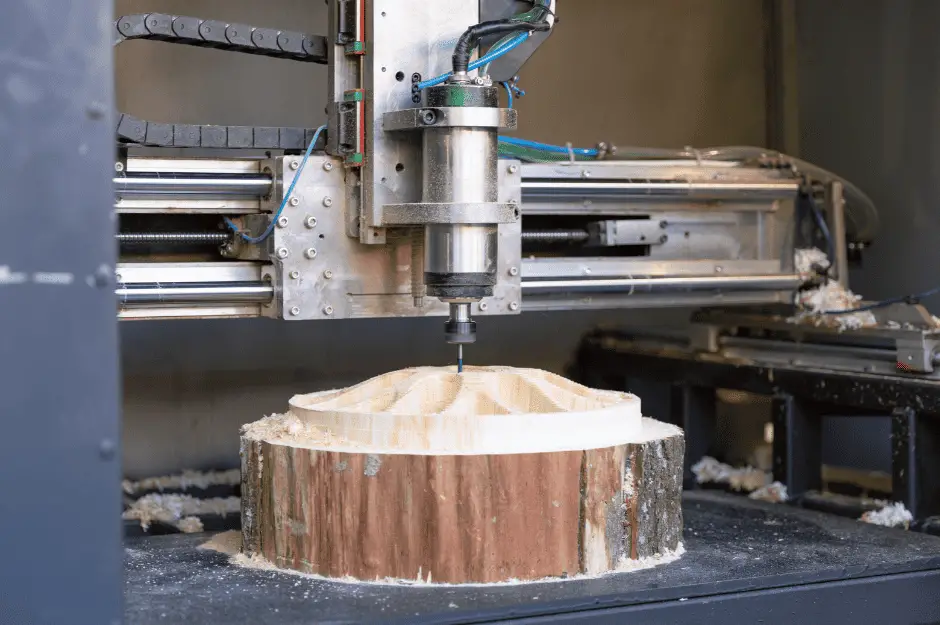
In the realm of CNC machining, G-code commands play a vital role in controlling various aspects of the machine, such as motion, speed, and cutting operations. One of the primary categories of G-code is motion commands, which direct how a CNC machine moves and interacts with the workpiece. This section will focus on some common motion commands in G-code, specifically within the GRBL control system.
Motion commands are used to define the motion mode, as well as the paths, lengths, and angles of the machine’s movement. There are several commonly used motion modes available in GRBL, which include linear moves (G0, G1), clockwise arc moves (G2), and counterclockwise arc moves (G3).
G0: Rapid Linear Move
The G0 command is a rapid linear move that allows the CNC machine to move quickly from one point to another without cutting the workpiece. This is typically used for positioning the machine at the start of a cutting operation or to switch between different cutting paths.
G1: Linear Move
The G1 command, unlike G0, is a controlled linear move that is used when the machine is cutting the workpiece. The CNC machine moves at a user-defined feed rate while maintaining a steady cutting process.
G2, G3: Circular Moves
G2 and G3 commands direct the CNC machine to perform clockwise and counterclockwise circular moves, respectively. These are used for cutting arcs and circular features on the workpiece.
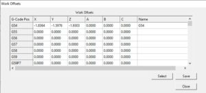
It’s also essential to understand that different coordinate systems can be set for motion commands. GRBL supports coordinate systems G54 through G59, where G54 is the default. These coordinate systems G54-G59 allow users to work with multiple setups or fixtures within a single program.
To sum up, motion commands within GRBL G-code dictate the movement patterns of a CNC machine during the cutting process. By understanding the various motion modes, CNC operators can efficiently program their machines and achieve the desired outcome for their workpieces.
Spindle and Tool Controls
Spindle Speed and Direction
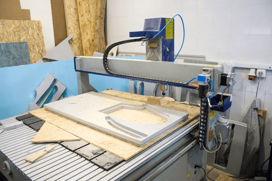
The spindle is an essential part of the CNC machine that rotates the cutting tool. In GRBL, g-code commands are used to control its speed and direction. The S command sets the spindle speed, which ranges from 0-1000 with default build settings. Two g-code commands are used to define the spindle’s direction:
M3: Sets the spindle pin to the PWM rate specified by theScommand. This rotates the spindle clockwise and sets the spindle direction pin high.M4: Sets the spindle pin to the PWM rate specified by theScommand. This rotates the spindle counter-clockwise.
Tool Length Offset
Tool length offset is a critical aspect to consider in CNC operations. G-code commands are used to designate the appropriate tool length offset, ensuring accurate cutting processes. The most commonly used commands for tool length offset include:
G43: Apply the specified tool length offset. This command requires an additional H-word to identify the offset number.G44: Apply the negative of the specified tool length offset, similar to G43 but with a negative value.G49: Cancel the current tool length offset, returning the tool to its original length.
To summarize, spindle and tool controls in GRBL play a vital role in CNC operations. Spindle speed and direction are controlled by g-code commands such as S, M3, and M4, while tool length offsets are managed through commands like G43, G44, and G49. These controls ensure the accuracy and precision of the cutting process in CNC machines.
Coordinate and Plane Settings
Coordinate Systems and Offsets
In CNC programming, it is essential to understand coordinate systems and how they affect the machine’s movements. The GRBL G-code commands play a crucial role in defining these systems. There are six predefined coordinate systems available in GRBL, defined by the commands G54 to G59. These coordinate systems are used to instruct the CNC machine about the part’s location and orientation on the work table.
For example,
- G54: Coordinate System 1
- G55: Coordinate System 2
- G56: Coordinate System 3
- G57: Coordinate System 4
- G58: Coordinate System 5
- G59: Coordinate System 6
To set the coordinate system, a programmer would simply include one of these commands in their G-code program. Once a coordinate system is set, any subsequent G-code commands will reference that coordinate system until a new one is selected.
In addition to the predefined coordinate systems, CNC machines have a workpiece coordinate system (WCS) which defines the working area’s origin. Offsets are used to adjust the WCS to accommodate different workpieces or tool setups. The G-code commands G10 and G92 are used for setting offsets, where G10 allows for more precise offset adjustments, while G92 offers temporary offset changes.
Plane Selection
When programming a CNC machine, it is necessary to select the working plane, which helps define the machine’s movements in a specific plane. GRBL G-code supports three plane selection commands that correspond to the Cartesian coordinate system planes:
- G17: XY Plane
- G18: XZ Plane
- G19: YZ Plane
The G17 command is the default for most CNC machines, as it corresponds to the XY plane, which is the most common working plane. However, G18 and G19 can also be used to achieve specific movements and operations on the XZ and YZ planes, respectively.
Selecting the appropriate working plane is crucial for ensuring accurate CNC machine movements and achieving the desired results. Careful consideration should be given to the program’s required movements and the machine’s capabilities when selecting a working plane.
Modes and Settings
Distance Modes
There are primarily two distance modes in Grbl G-code: Absolute Distance Mode (G90) and Incremental Distance Mode (G91). These modes dictate how the CNC machine’s coordinates are interpreted while executing a G-code program.
- Absolute Distance Mode (G90): In this mode, all coordinates specified in the G-code are considered to be absolute positions relative to the machine’s origin. When using G90, the machine will always move to the exact position specified in the code.
- Incremental Distance Mode (G91): In contrast, G91 operates on relative coordinates. Each movement command in the G-code specifies the distance the machine should move from its current position. This mode is helpful for making repeated, incremental motions.
Arc IJK Distance Mode
The Arc IJK Distance Mode is a feature in Grbl G-code that helps in creating arcs and circles using G02 (clockwise) and G03 (counter-clockwise) commands. The I, J, and K parameters define the center of the arc relative to the starting point. These parameters can be expressed in either absolute or incremental coordinates, depending on the distance mode active during the program execution.
For example, in G-code:
- Arc clockwise:
G02 X10 Y10 I5 J5 - Arc counter-clockwise:
G03 X20 Y20 I10 J10
These commands instruct the machine to draw an arc from the current position to the X10, Y10, and X20, Y20 coordinates, respectively, with the specified I, J, and K values as the arc centers.
Feed Rate Mode
The Feed Rate Mode in Grbl G-code determines how the feed rate (speed of the tool) is controlled during the execution of a program. There are two main feed rate modes: Units per Minute (G94) and Inverse Time (G93).
- Units per Minute (G94): In this mode, the feed rate is set by specifying a value in units per minute. This is the most common mode used in CNC machining, as it provides a consistent feed rate throughout the operation. For example,
F100sets the feed rate at 100 units per minute. - Inverse Time (G93): In contrast, G93 mode calculates the feed rate based on the inverse of the time it should take to complete a move. The feed rate is determined by specifying the total time for a movement. For example,
F2sets the feed rate so that the operation takes 2 seconds to complete.
Understanding these modes and settings in Grbl G-code will help in creating efficient and accurate CNC machining programs.
Homing Cycle and Machine Settings
The homing cycle in GRBL is an essential process for setting up a CNC machine to work accurately. It allows the machine to establish a reference point for its coordinates, making it easier to execute G-code commands and maintain precise movements. To initiate the homing cycle, the G28 command is used, which moves the machine axes to their respective home positions source.
GRBL settings are critical in determining the machine’s behavior during the homing cycle. These can be modified using the $23 setting, which allows the user to define the home position in various ways:
$23=0: Default setting, home location at the top right of the work area, with the spindle fully retracted.$23=1: Home location at the top left of the work area.$23=2: Home location at the bottom right of the work area.$23=3: Home location at the bottom left of the work area.$23=4: Home location with the spindle fully down.
Aside from the homing settings, GRBL has numerous other settings that affect a CNC machine’s operation. These settings include:
- Motor step settings: Configure the steps per millimeter, steps per revolution and enable/disable inverted axes.
- Limits settings: The ability to enable hard/soft limits and adjust the maximum travel distance for each axis.
- Feed rates: Determine the maximum and default feed rates for the machine during various operations.
- Spindle settings: Manage the spindle speed and direction controls.
- Acceleration settings: Modify the acceleration rates during machine movements.
These settings are vital for ensuring that the CNC machine operates accurately and efficiently. Proper adjustments in these parameters will help users achieve desired results when working with various materials and G-code commands. By understanding the homing cycle and GRBL settings, users can optimize their CNC machines for top performance and precision during operation.
Additional G-Code Features
Comments and Printing
Grbl supports comments which can be added to G-code files to provide additional information, clarity, or instructions for the user. Comments are inserted within parentheses and are ignored by the G-code parser, allowing the file to be executed without interruption.
G-Code Parameters
G-code parameters are values assigned to specific G and M commands within the code, controlling aspects such as feed rates, spindle speeds, and axis movements. Parameters may include integers, decimals, expressions, or coordinate values, providing flexibility and customization. Here’s an example of G-code command with parameters:
- G1 X10 Y10 F200
This command moves the machine to the X10, Y10 position at a feed rate of 200 units/minute.
Laser Mode
Grbl v1.1 introduces a Laser Mode which optimizes the performance of laser engravers and cutters. When enabled, this mode adjusts motion planning and allows for dynamic laser power control. Grbl’s laser mode can be toggled with the command:
- $32=1 (Enable laser mode)
- $32=0 (Disable laser mode)
Initialization and Parsing State
Grbl goes through an initialization process on startup, verifying important settings and establishing the parsing state. The parser state contains information about the currently active G-code modal groups, such as motion, plane selection, and units. Users can request the parser state with the command:
- $G
This will return the active state of G-code modes, providing useful feedback on the machine’s current status.
Firmware, Build Info, and P1 Configuration
GRBL is an open-source firmware that enables motion control for CNC machines. It is a powerful tool that translates G-code commands into electrical impulses for the motors controlling the movements and speeds of CNC machinery. GRBL is compatible with a variety of hardware, including Arduino boards, making it a popular choice for low-cost, high-performance CNC controllers.
The build info of GRBL provides essential information about the current version, date of creation, and other details that are useful for users to know. Notably, GRBL 1.1f (the version used in this article) has undergone several updates and improvements since its inception. Users can view the build information of their GRBL firmware by sending the command $I through their control software.
The P1 Configuration is a crucial aspect of setting up and calibrating a CNC machine. P1 (also known as G10 L2) is a non-modal command used in GRBL for setting the tool length offset for the current tool. It helps users to define specific parameters for their machine and improve the accuracy of their CNC operations.
A few tips for configuring P1 in GRBL:
- Ensure your CNC machine firmware is updated to the latest version.
- Use a reliable control software compatible with GRBL, such as UGS, Candle, or bCNC.
- Always double-check your input values and settings before starting a CNC operation.
- If you encounter any issues or errors, consult the GRBL documentation for troubleshooting and configuration guidance.
By understanding and correctly configuring firmware, build info, and P1 for GRBL, users can maximize the potential and performance of their CNC machines.

