cnc programming for beginners
In this article I will be explaining the basics of contour programming including linear interpolation. This is the use of straight lines in G code.
I will be giving basic examples of various approaches to create different shapes, hopefully giving you the knowledge to create whatever profile you will need.
The most basic example would be a single linear line between two points. Consider the drawing below and I will show the code needed to make the cnc machine mill the line.
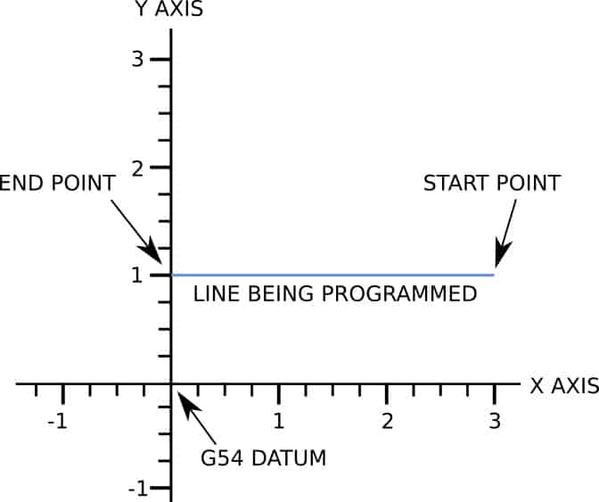
The linear commands that will ‘draw’ the line are shown in bold.
%
OMILL-LINE
G17 G20 G40 G49 G80 G90 (SAFETY LINE)
T1 M06 (TOOL CALL)
G00 G54 X3. Y1. S2000 M03 ( PRE POSITION AT START OF LINE)
G43 H1 Z1. (MOVE TO Z SAFE POINT)
G00 Z.1 (RAPID TO .1” ABOVE Z ZERO)
G01 Z-.01 F2. (FEED DOWN TO -.01”)
X0. F20. (MILL LINE AT A FEED RATE OF 20.)
G00 Z1. (MOVES AT RAPID TO SAFE Z)
M05 (SPINDLE OFF)
G91 G28 X0. Y0. Z0. (MOVE TO HOME POSITION)
G90 (RE-ESTABLISH ABSOLUTE PROGRAMMING)
M30 (FINISH PROGRAM, REWIND AND STOP)
%
As you can see I copied and pasted the header and footer from the G code for Dummies lesson and inserted a few lines and edited the start position.
You may have noticed that on the line, X0. F20. I did not re-type the G01, this is because that command is modal.
Modal means it stays active until another command is specified. For example, the next line is a G00, this cancels the G01 and the G00 will remain active until that command is “overwritten”.
Looking again at the line, X0. F20. you will notice there isn’t a Y axis position specified.
This is because the same rules apply to positions, the machine will keep the existing value until another is specified.
I will now show an example of a rectangle, you should now be getting the idea of how to do this yourself.
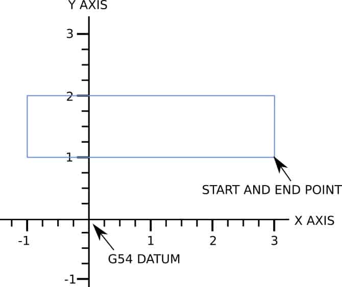
The linear commands that will ‘draw’ the rectangle are shown in bold.
%
OMILL-RECTANGLE
G17 G20 G40 G49 G80 G90 (SAFETY LINE)
T1 M06 (TOOL CALL)
G00 G54 X3. Y1. S2000 M03 ( PRE POSITION AT START OF LINE)
G43 H1 Z1. (MOVE TO Z SAFE POINT)
G00 Z.1 (RAPID TO .1” ABOVE Z ZERO)
G01 Z-.01 F2. (FEED DOWN TO -.01”)
X-1. F20. (MILL LINE AT A FEED RATE OF 20.)
Y2.
X3.
Y1.
G00 Z1. (MOVES AT RAPID TO SAFE Z)
M05 (SPINDLE OFF)
G91 G28 X0. Y0. Z0. (MOVE TO HOME POSITION)
G90 (RE-ESTABLISH ABSOLUTE PROGRAMMING)
M30 (FINISH PROGRAM, REWIND AND STOP)
%
As you can see programming a rectangle is exactly the same as a single line but with the extra coordinates added in.
The linear G01 moves only need to specify changes from the previous line.
The G01 command, the feed rate and the unspecified axis moves are used again by the machine until a new value is given.
This rectangle program does not account for the size of the cutter, if you needed the part to be the same size as the drawing there are two different ways this can be done.
The first and most common is to change the coordinates of the program to account for the radius of the cutter being used.
This is how your programs would be processed if CAM software was outputting the G code.
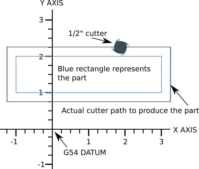
The example program below shows the rectangle being milled with a ½” diameter cutter. The program has been altered to account for the radius of the 1/2″ endmill.
%
OMILL-RECTANGLE
G17 G20 G40 G49 G80 G90 (SAFETY LINE)
T1 M06 (TOOL CALL)
G00 G54 X3.25 Y.75 S2000 M03 ( PRE POSITION AT START OF LINE)
G43 H1 Z1. (MOVE TO Z SAFE POINT)
G00 Z.1 (RAPID TO .1” ABOVE Z ZERO)
G01 Z-.01 F2. (FEED DOWN TO -.01”)
X-1.25 F20. (MILL LINE AT A FEED RATE OF 20.)
Y2.25
X3.25
Y.75
G00 Z1. (MOVES AT RAPID TO SAFE Z)
M05 (SPINDLE OFF)
G91 G28 X0. Y0. Z0. (MOVE TO HOME POSITION)
G90 (RE-ESTABLISH ABSOLUTE PROGRAMMING)
M30 (FINISH PROGRAM, REWIND AND STOP)
%
The alternative is to program the coordinates the same size as required and use a cutter offset command, such as G41, to offset the tool.
The appropriate size tool dia or radius would be added to the tool offset table.
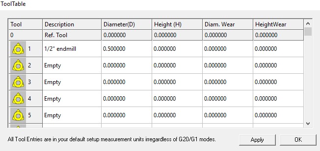
The advantage of doing the program this way is that different sizes of cutters can be used with the same program.
The only change you have to make is the diameter in the tool offset table.
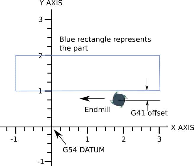
One point to note, when using tool offsets, lead in and lead out lines have to be added to enable the tool offsets to be “switched on” and “switched off”.
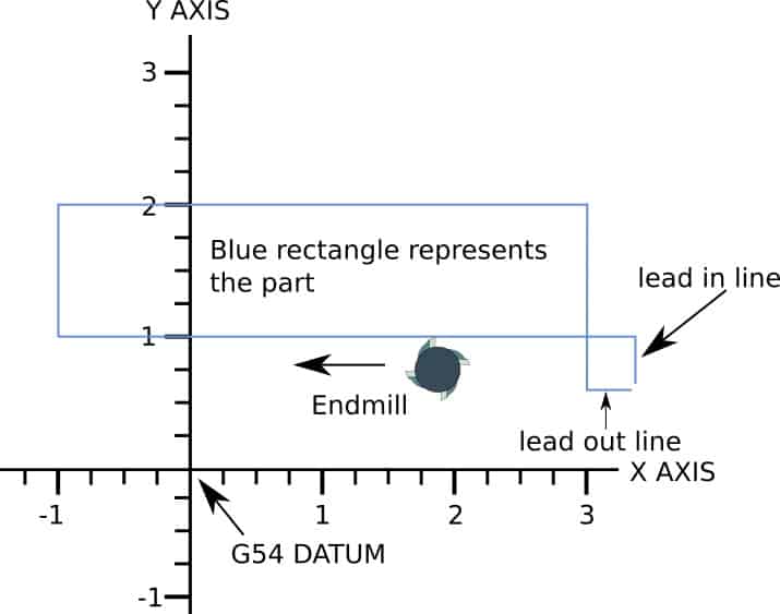
So the program with lead in and lead out lines would look like this:-
%
OMILL-RECTANGLE
G17 G20 G40 G49 G80 G90 (SAFETY LINE)
T1 M06 (TOOL CALL)
G00 G54 X3.3 Y.5 S2000 M03 ( PRE POSITION AT START OF LEAD IN LINE)
G43 H1 Z1. (MOVE TO Z SAFE POINT)
G00 Z.1 (RAPID TO .1” ABOVE Z ZERO)
G01 Z-.01 F2. (FEED DOWN TO -.01”)
G41 D1 Y1. F20. (TURN ON CUTTER OFFSET, LEAD IN TO PART)
X-1.
Y2.
X3.
Y.75
G40 X3.5 (TURN OFF CUTTER OFFSET WHILE MOVING AWAY)
G00 Z1. (MOVES AT RAPID TO SAFE Z)
M05 (SPINDLE OFF)
G91 G28 X0. Y0. Z0. (MOVE TO HOME POSITION)
G90 (RE-ESTABLISH ABSOLUTE PROGRAMMING)
M30 (FINISH PROGRAM, REWIND AND STOP)
%
Another important point is that the lead in and lead out lines have to be longer than the radius of the cutter being used. If they are shorter the program will force an error.
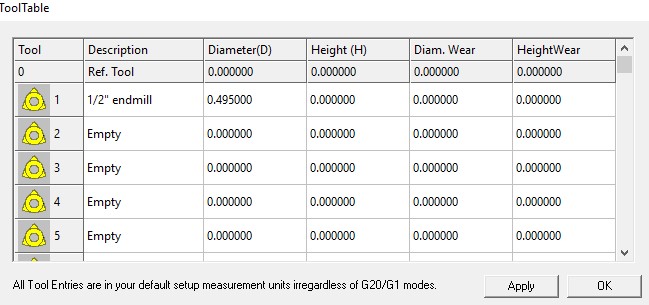
The advantage of using a G41 offset in your program is the ability to adjust the size of the part you are machining. Adjusting the diameter in the offset table so that it does not match the size of the tool will “fool” the machine to change the size of the part.
Increasing the diameter in the tool table has the effect of making the part bigger. Reducing the dia will make the part smaller than programmed.
This enables you, the operator, to make the part bigger for the first pass so that it can be measured and then adjusted and re-run to produce an accurately sized part.
For example, if a ½” endmill was being used and you needed the part to be .005” smaller than programmed, a value of .495” would be entered into the tool table.
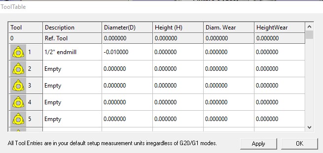
This process of adjustment can also be used with the previous programming example where the program is altered to account for the tool radius. In this scenario you would use G41 in the program but the offset value in the tool table would be adjusted by the amount needed. E.g. if you wanted -.01” of stock taking off the part, a value of -.01” would be entered in the tool table.
Facing
Facing a part is the perfect process to use linear interpolation. Facing means to create a flat surface on the top of a workpiece, which could then be used as your Z datum reference plane.
A typical facing pattern will look something like this drawing below.
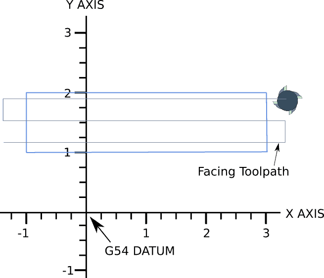
The program will look very similar to the examples already shown in this article. One difference will be the Z depth. For this type of program you will typically start above the Z zero datum and mill down to finish at the Z datum.
Once this has been done the rest of the operations can be applied to the part. E.g. any holes that need drilling or the profile applying, all the way to completing the part.
A program for facing will look similar to this below which describes the drawing above.
%
OMILL-FACING
G17 G20 G40 G49 G80 G90
T1 M06
G00 G54 X3.3 Y1.8 S2000 M03
G43 H1 Z1.
G00 Z.1
G01 Z0. F2.
X-1.3 F20.
Y1.5
X3.3
Y1.2
X-1.3
G00 Z1.
M05
G91 G28 X0. Y0. Z0.
G90
M30
%
You will notice that a facing program is very basic because it does not need any offsets applying. It is just a series of basic linear moves at one Z plane. The only calculating you will need to do is to make sure the cutter paths force the tool to overlap the previous path.
A common amount of overlap to use when facing is about 75% of the cutter diameter.
This isn’t a critical size to achieve, it can be approximate, it’s just a general rule of thumb.
Generally speaking, the bigger the diameter of tool the better when it applies to facing. Just be aware of what your hobby cnc machine is capable of with regard to the cutting forces applied to it. If you find your machine is struggling and you are getting a bad finish, use the same diameter of cutter but increase the overlap.

If you are interested in furthering your programming skills I can recommend learning from an online course.
Udemy have quite a few to choose from including ‘Foundation to Cnc Programming using GCode‘ , which covers a lot of the basic programming processes.

G codes
- G00 = rapid movement
- G01 = move at the specified feedrate
- G02 = clockwise arc or circle movement
- G03 = counter clockwise arc or circle movement
- G17 = X Y plane selection
- G20 = coordinates in inches
- G21 = coordinates in MM
- G28 = home position return
- G40 = cutter compensation cancel
- G41 = cutter compensation left
- G42 = cutter compensation right
- G43 = tool length compensation on
- G53 = cancel work offsets
- G54,G55,G56,G57,G58 and G59 = work offsets
- G80 = cancel canned cycle
- G81 = basic drilling canned cycle
- G83 = peck drilling canned cycle
- G90 = absolute programming
- G91 = incremental programming
M codes
- M00 = program stop
- M01 = optional stop
- M03 = spindle on
- M05 = spindle off
- M06 = tool change
- M30 = end of program, rewind and reset
- M97 = subroutine call
- M98 = subprogram call
- M99 = subprogram end


