In this post I am going to explain what cnc offsets are, how they are used, and how they relate to a machine reference point or home position. But first I should begin by explaining the basic rules that cnc machines operate by…
Cartesian coordinate system – cnc axis directions
“A Cartesian coordinate system is a coordinate system that specifies each point uniquely in a plane by a set of numerical coordinates”. Source.
To specify positions in three dimensional space, this system needs to have three axes, X , Y and Z.
The point where these three axes meet is called the origin.
If you can remember back to when you were at school and you drew points on graphs, cnc machines use the same system to move to specific points in its work area.
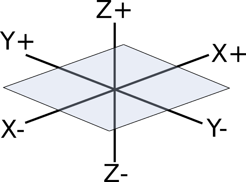
There is an X axis, travelling left to right, a Y axis travelling front to back and a Z axis travelling up and down. If you have a position for each axis, x y and z, you can plot that exact point in space from the origin.
Cnc axis explained
Using these positions you can tell a cnc machine where to move to.
If you specify a positive X value e.g. X15. the position will be to the right of the origin. If you specify a negative X value e.g. X-1.5 it will be to the left of the origin.
If you specify a positive Y value e.g. Y8. the position will be forward of the origin, away from you. If you specify a negative Y value e.g. Y-1.5 it will be behind the origin, more toward you.
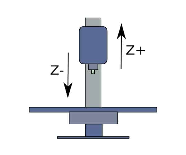
If you specify a positive Z value e.g. Z2. the position will be above the origin. If you specify a negative Z value e.g. Z-1.5 it will be below the origin.
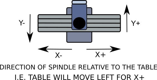
One other important point to note is that the direction of travel refers to the movement of the tool.
So if it is the table that moves, an X positive move will need the table to move to the left. This makes the tool move to the right in relation to the part you are machining.
Likewise, to make a Y positive move, the table will need to move toward you. Moving the tool in a positive direction in relation to the part on the table.
What is a machine reference position?
A machines reference position or home position, as it is sometimes referred to, is the point at which all 3 axes read Zero. This is usually set as far as the machine can move in a positive direction in all 3 axes.
It can be set anywhere you want but you definitely want it all the way up (positive) in Z. Also having the machine go in positive directions for X and Y will get the tool as far away from the part as possible when you “home” the machine.
This makes it a lot easier to set up your parts because when you home the machine, the spindle moves out of the way.
Once you have set your machines reference position it should not change. You will not need to change it for programming reasons at all, ever.
Most, if not all, industrial machines have limit switches, these tell the software that the machine is about to run out of available movement, preventing any damage. These limit switches are also used to locate the reference or home position for the machine.
Most hobby cnc machines do not come equipped with limit switches, but the software we use has limit switch functionality. This means they can be added if you want.
This is not necessary if you do not want to fit them. I have addressed this “great debate” in another article here.
What you should always do is home your machine before you switch it off. This is because when you switch it back on, where the machine is when you start it up is where your “new” home position will be.
Keeping the home position the same as always means you can pick up where you left off if you did not finish a part or project during your last session.
Get into the routine of including a homing command at the end of every program you run, that way you don’t have to remember to do it using MDI or manually.
What are cnc machine offsets?
Cnc machine offsets or work coordinate system (WCS) are positions you set that are referenced from your machines home position.
You can set multiple offsets in a program.This is usually done when machining several parts at the same time. The offset positions are given Gcode numbers, most commonly G54 through G59.
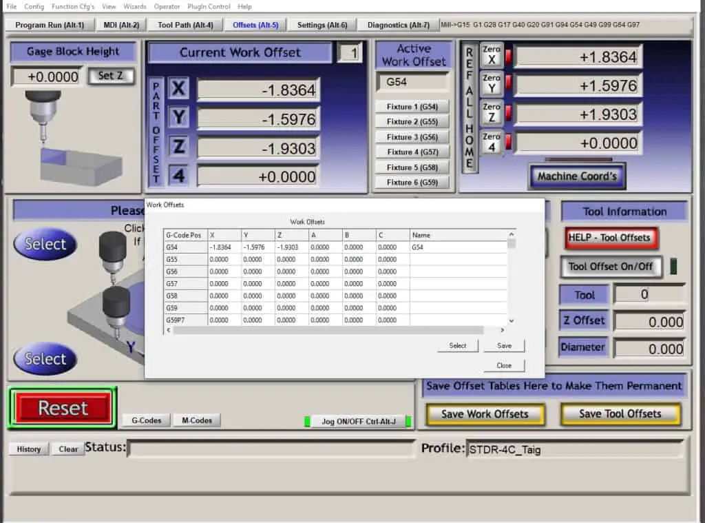
When you set an offset, for example G54, you will locate a position for each axis on the part to be machined. Setting these positions to G54 in the machine software offset table. G54 will then be displayed as an X, Y and Z value that is a set distance from the machines reference point.
When an offset is activated in your Program, the machine control software will know where your part is relative to its home position. It will then compensate the readout to show where the machine is with regard to the active offset.
This enables you to visually confirm your tools position relative to the part datum and not the machines home position. If you cancelled the offset in the program with a G53, (offset cancel command), the machine would run the program relative to its home position. Also the readout in the machine control software would reflect this change.
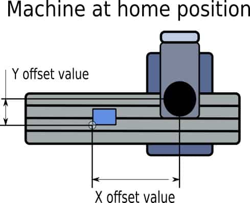
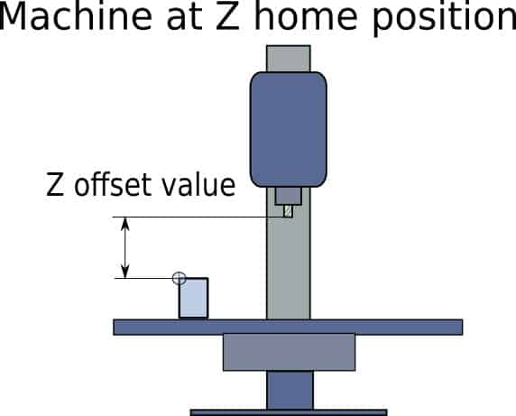
So what would your offset values look like? Well, if you positioned your machine reference point at all three axes most positive position, all three of your offset values will be negative. Everytime and with every offset you set.
Knowing this will enable you to see if something is very wrong when you give your offset positions a quick visual check.
For example, if your cnc machine has about 4” of Z axis movement and your G54 Z offset value is Z-5.423, and you set it to the top of your part, you know it has been set incorrectly and you can change it.
Doing these types of checks are vital if you want to prevent crashing your machine, possibly damaging it.
I have written an article explaining how to set your datums here.
A quick overview of setting your offsets to machine a part
- Fixture the part to be machined to the table
- Load a tool such as an edge finder into the machine spindle
- Use it to pick up the designated datum edge of the part in X and Y
- This is done by referencing the position in your software when the edge finder is located against the datum edge. That value will then be stored in the offset table.
- Repeat for the second axis
- The Z can be set in several ways. The most basic way is to load a tool in the spindle then manually move the tool down to just touch the datum face. The position is then stored in the relevant offset table.
- Each axis will now have an offset value from the machine reference position stored in the software offset table. This is now ready to be called up and used by a Gcode program.


