how to use g28 g code
The G28 G code is one of those commands that can confuse and be the cause of an unwanted crash or near miss. But it is a command I use in every program I write and is vital to how I run my desktop cnc machine.
Once you understand how to use it you will jump for joy, honest.
The G28 G code command will return your machine to its home position or machine reference position.
It will do this via an intermediate point that you specify.
The intermediate point will be referenced from the active work offset e.g. G54, G55 etc
Before I give you some examples of how the G28 command works I should explain two more G codes you need to understand that I will be using with G28.
- G90
- G91
G90 specifies Absolute programming mode. The machines positioning is always referenced from the active part datum.
G91 specifies incremental programming mode. The machines positioning is always referenced from its previous position.
We can use these commands with the G28 to make it behave slightly differently.
G28 is used along with X Y and Z movements, you can use just one or all of the axis movements.
First of all I will show and explain the way I use G28.
G91 G28 X0. Y0. Z0.
The G91 is used to put the machine in incremental mode. Doing this will prevent the machine from moving to its intermediate position. Incremental means the machine will move the amount specified from its previous position, I have specified zero for each axis.
Therefore the machine will move Zero distance, then it will go to its home position. In a nutshell, using the command this way will make the machine move straight to the home position.
The fact that I specified all three axes means it will go to the home position of all three axes.

I always use it this way in every program I write. It is good practice to send your machine to its home position in all axes when it has finished running a program.
When using it this way it is important to always retract your tool in the Z axis to a position above the highest point of the part you are machining.
This ensures that your machine does not try to pass through the job on its way home.
If you wanted to retract the Z axis first and then home the X and Y axis you could do that using two separate G28 commands like this:-
G91 G28 Z0.
G28 X0. Y0.
The G91 command only has to be specified on the initial line because it is a modal command.
This means it remains active until it is cancelled. In this situation you would want to cancel it on the next line using a G90 to re-establish absolute programming mode.
If you don’t specify G91 you have to be careful with what axis moves you decide to use. They will be different with every program you make.
Here are a few more examples to help show you what this command can do,
G91 G28 Z0.
In the example above the machine will move straight up to the Z axis home only.
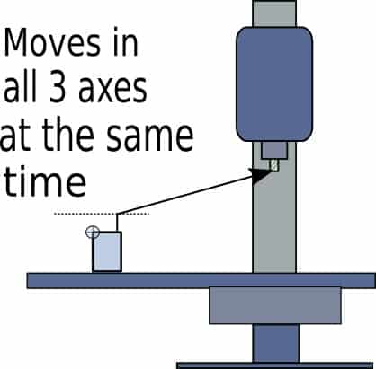
G28 X0. Y0. Z1.
In the example above the machine will move to its part datum in X and Y while moving to 1” above the active part datum before going to its home position in all three axes. One thing to note is that it will move to its intermediate point in all three axes at the same time. It won’t move up to Z+1 then move in X and Y. So it could pass through the part on its way to the intermediate point.
G28 Z0.
In the example above the machine will rapid to its Z zero part position before moving to its Z home position only. This is a good example of what not to do unless you enjoy scaring yourself.
So if any of the examples tell you anything it should be to use G28 in incremental mode (G91) from a safety line above the highest part of the project you are machining.
Another important point is to always re-establish G90 (absolute programming) after the G28 command if you specify G91.
So the end of a typical program could look like this:-
G00 Z1. M09 (move up in Z 1” above the Z datum, turn off coolant)
M05 (stop the spindle)
G91 G28 X0. Y0. Z0. (rapid move to home position)
G90 (re-establish absolute programming mode)
M30 (finish program and rewind to the beginning and stop)
% (identifies the end of the program)
The excerpt above could be used in most programs as a “footer”. This could be saved as a sample program along with a “header” for the beginning of a program.
To write a quick G-code program you could make a copy of the header and footer program then fill in the middle with your milling or drilling cycle.
This is a really quick method for writing a program, you should even keep full programs and title them descriptively, copy, edit the tool path for whatever you need.
Writing programs this way is quicker than using cad/cam but limited to only basic programming such as drilling or simple profile shapes.
An example of a “header” could look something similar to this:-
% (Identifies the start of the program)
ODRILL (program name)
G17 G20 G40 G49 G80 G90 (safety line establishing important G codes)
T1 MO6 (Tool call and tool change commands)
G00 G54 X0. Y0. S2000 M03 (X and Y pre-position line)
G43 H1 Z1. (Tool length offset command and Z pre-position line)
The safety line above contains the following G codes:-
- G17 = X Y plane selection
- G20 = Programming in inches (G21 is metric)
- G40 = Cancels tool radius or diameter compensation
- G49 = Cancels tool length offsets
- G80 = Cancels any canned cycles
- G90 = Absolute programming
The tool call line is asking for Tool 1 and M06 is telling the machine to pull tool 1 from the tool changer. Your hobby mill will not have a tool changer but that is ok, the command won’t create an error or stop the program from running.
Most Cam post processors will put these commands in the program anyway, you don’t have to change it.
The X and Y pre-position line is specifying rapid moves (G00), and establishing G54 as the active datum offset. This line also tells the machine to move to X zero and Y zero, switching the spindle on (M03), with an RPM of 2000, (S2000).
Only a few hobby cnc mills will have a variable speed spindle but leaving the command in will not cause any errors. It will let you know approx what speed you ran the spindle at if you use the program again. You just set the speed manually yourself.
The last line in our example program “header” switches on tool length compensation, G43, specifying H1 offset length. Then it commands the z axis down to 1” above the Z datum.
Again, most hobby mills do not have tool changers but specifying a tool length offset is a good habit to use and most post processors will output a program with it as shown. Just have your tool length set as Zero.
My tool length offset article is here, It explains this in more detail.
Put the header and footer together and it will form the basis of a program you can copy and paste to quickly write and edit for a new project.
The header and footer below would be ideal for adding to G-Code created by a simple G-code generator like the one included in the vector software ‘Inkscape’ or even a cnc project from fusion 360 .
%
ODRILL
G17 G20 G40 G49 G80 G90
T1 MO6
G00 G54 X0. Y0. S2000 M03
G43 H1 Z1.
(insert the main program here)
G00 Z1. M09
M05
G91 G28 X0. Y0. Z0.
G90
M30
%
If you haven’t seen any G code before and all these codes have you scratching your head take a quick look at my G code programming article and an explanation of cnc terminology.

