Cnc Hobby Projects
The problem with building a scale model is finding commercially available parts that represent the real subject. Benchtop cnc machines enable you to produce your own parts exactly as you need them.
They are accurate enough to manufacture precision moving parts or to replace inaccurate or damaged manufactured parts.
It is also common to use a cnc router to manufacture your own design rc models using milling tools or a laser cutter.
One popular cnc hobby project question is how to make landing gear for rc aircraft. Replacing wire legs on a scale aircraft goes a long way to improving its realism.
Commercially available units are generic and designed to be used in any model, so you have to make your own.
This is where a small benchtop cnc machine excels.

Although this might not be a cnc project for beginners it isn’t beyond the abilities of someone with a small amount of cnc knowledge and a set of digital calipers.
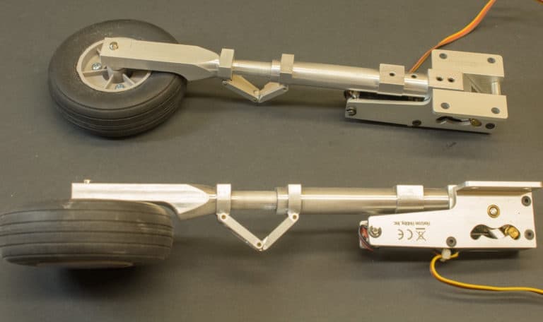
I made this set for a kawanishi N1K2-j model a while ago. I didn’t take any photos of the construction but the pictures should give you a good idea of how they were made.
I followed the basic principles of any cnc project outlined in ‘how to run a cnc machine’.
I started off deciding how I was going to design them, following the outline of the full size aircraft.

Then I created my own drawings, ensuring I had the tools to complete them.
This means checking I had the correct sized drills, cutters and whether my little lathe and mill were big enough.
Sometimes a design has to be changed just to suit the size of your machine and what tools you have available.
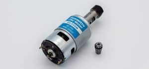
These parts started from round stock of aluminum.
Most of the initial operations were done on a manual taig lathe.
The hardest part was drilling out the inside of the main strut to accept the lower leg. The taig lathe is quite short and I had to reduce the length of a drill to make it fit.
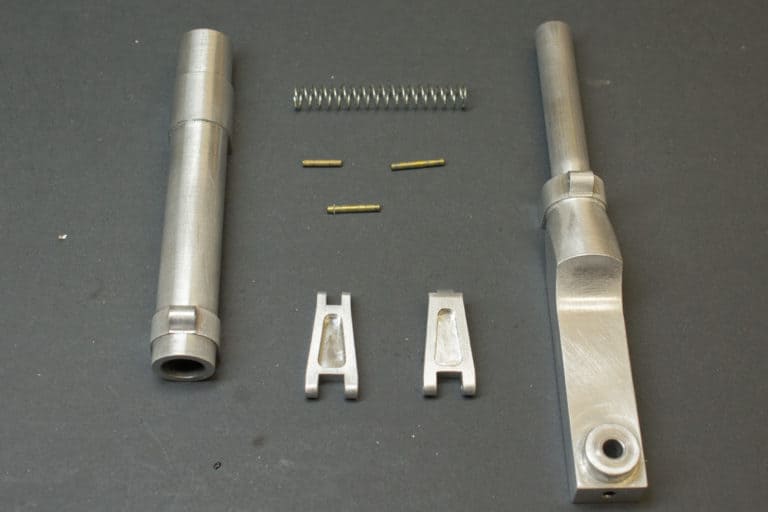
The sliding fit had to be accurate so I drilled the hole first then later turned the male part to fit the finished size.
This way I didn’t have to worry about the drill cutting slightly oversize.

Once the turning was completed the struts were mounted in the rotary 4th axis on the cnc mill to square off the area where the wheels are mounted.
This area was straightforward and only involved basic G-Code programming.

The next parts to be machined were the scissor links.
Again the programming was quite straightforward once the design and dimensions were carefully thought through and finalised.
The scissor links were initially machined ‘edge up’ in a vise so the narrow profile could be milled and the small hinge holes drilled.
The remaining operations were completed gripping on the excess stock in various orientations in a vise.
Then they were cut off the stock that was being held by the vise and turned around to finish the opposite edge.

One other issue I had to deal with was the position of the mounting hole in the retract units.
It needed repositioning to accommodate the larger diameter of the main struts.
I decided it would be easier to copy the existing pivot blocks and keep the originals, positioning the hole in the bottom to suit the new struts.
You can see the original pivot block in the picture above with the one I machined installed in the unit.

Scratch building models
Here is an example of using a cnc machine to achieve an accurate cutout in thin plywood. I needed to produce a window for a model Cessna, the acetate that was going to be used to represent the glass needed to be recessed.

To make this easier I programmed the profile of the window to produce an accurate shape on my cnc machine.
This was then repeated using a reduced tool diameter offset and reduced Z axis depth to achieve the recess.
The profile was then mirrored to complete the opposite side.
This was done before the panel was glued to the existing airframe.

I have many tutorials on this website dedicated to educating hobbyists about diy cnc machining.
The techniques I have talked about here are explained in detail on posts like ‘G-code programming for dummies’ and ‘M99 cnc code’.
Hopefully this post will give you ideas on how a benchtop cnc machine can help with your hobby and take it to the next level.