g code loop
If you are reading this you are probably new to cnc programming and may be wondering how to program subroutines and what they can do. You may have heard them described as G code loops or G code repeats.
The M99 M code actually works in conjunction with the M98 M code and the M97 M code.
M97 = subroutine call
M98 = subprogram call
M99 = subprogram end
A very important note here is to warn you that not all Cnc operating software programs work in the same way.
They can have different rules for using subroutine and subprogram calls. For example mach3, the software I use, does not recognise M97. It uses M98 for both subroutine and subprogram calls. You will have to check the manual for your software.
M97 Cnc Code
To use the M97 the subroutine needs to be in the same program that you are running, it has to be positioned after the M30 or M02 at the end of the program.
To use M98, the subprogram is separate and usually needs to be in a designated folder on your PC.
M97 and M98 can be used to enable you to mill a deep profile by pecking down in depth multiple times.
This is achieved by using an incremental Z axis peck depth and calling up the profile as many times as needed. The profile then runs the required amount of times going deeper with each pass.
Another use is to create simple 3D shapes, more commonly referred to as 2.5D shapes.
This may be a radius or chamfer along a horizontal edge. In this instance a profile is translated using an incremental move along the X or Y axis.
A typical M97 G code line will look like this:-
M97 P10 L12
The P number signifies the line number to go to which is prefixed with an N.
E.g. N10
The L number is the amount of repeats you want the subroutine to be repeated. In the line of code above it will be repeated 12 times.
What is a Subprogram in Cnc?
The answer to that question is the M98 Cnc Code. It will call up a seperate program and not a sub routine at the end of the program.
Using the M98 is the same as using the M97, but instead of using an N number after the P, a program name is used.
M98 P1234 L8
In this instance the program name 1234 will be called. The start of the sub program will have the prefix O in front of the name. So in this case the first line of the program will be O1234.
I use Mach3 software and M98 is used for subroutines as well as subprograms. So the examples below reflect that. If your software uses M97 just change the programs accordingly.
M99 Cnc Code
The M99 is used at the end of both subroutines and subprograms. It tells the G code software to go back and run from the M97 or M98 code.
A subroutine or subprogram only need to contain the relevant lines of code, all the tool information and home commands etc are in the main program.
So in some cases they will only be a couple of lines long with an M99 as the final line.
In the example below I am using M98 to call a subroutine. This is how Mach3 software operates. It uses the same rules as a subprogram call but you have the choice of putting it in the subroutine folder or after the M30.
cnc subprogram G code example
%
OMILL-RECTANGLE WITH ARCS
G17 G20 G40 G49 G80 G90
T1 M06
G00 G54 X-2.6 Y-.25 S2000 M03
G43 H1 Z1.
G00 Z.1
G01 Z0. F10.
M98 P10 L10 (SUB PROGRAM CALL 10 TIMES)
G90 G00 Z1.
M05
G91 G28 X0. Y0. Z0.
G90
M30
%
(subprogram)
O10 (THE LETTER “O” IS USED BEFORE THE PROGRAM NAME)
G91 G01 Z-.025 (INCREMENTAL Z DEPTH FOR EACH PASS)
G90 X-2.25 F20.
Y1.
G02 X-2. Y1.25 R.25
G01 X2.
G02 X2.25 Y1. R.25
G01 Y-1.
G02 X2. Y-1.25 R.25
G01 X-2.
G02 X-2.25 Y-1. R.25
G01 Y.25
X-2.6
G00 G91 Z1.
G90 X-2.6 Y-.25
G91 Z-1.
M99 (RETURN TO M98)
This program is a modified version of the rectangle with rads shown in the article “circular interpolation in Cnc”. I have changed it to repeat 10 times, each time plunging an extra .025”. This will take the total depth of the rectangle to Z-.25” deep.
The plunging is achieved by using an incremental move of Z-.025” shown in the line G91 G01 Z-.025.
It is important to note that on the very next line I have used a G90 to take the program back to absolute mode.
If this is not done the program will continue in incremental mode and a minor disaster would occur!
Using this technique is perfect for improving the versatility of simple G-Code generators like the one included in the Vector software ‘Inkscape‘.

In this next example we will again use a program from the previous lesson. This time I will change the incremental ramping program. I have been able to remove all the copy and pasted lines and replace them with a short three line subroutine.
%
OMILL-RAMPING CIRCLE
G17 G20 G40 G49 G80 G90
T1 M06
G00 G54 X0. Y0. S2000 M03
G43 H1 Z1.
G00 Z.1
G01 Z0. F5.
G01 G41 D1 X1. Y0. F20.
M98 P20 L25 (CALLS SUBROUTINE X 25)
X0. Y0. I-1. J0.
G90 G01 G40 X0. Y0.
G00 Z1.
M05
G91 G28 X0. Y0. Z0.
G90
M30
%
(subroutine)
O20
G91 G03 X0. Y0. I-1. J0. Z-.02
M99 (RETURN TO M98)
This program will now interpolate a circle Z-.5” deep.

2.5D Cnc
Using subroutines will enable you to program a simple single line move and translate it along an axis. This technique will also use G91 incremental mode.
Learning how to use this method will open up a huge amount of flexibility in what you can machine without having to use cad/cam software.
I will show a few basic examples in this lesson to give you an idea of what can be done.
The first example is a chamfer. The values in any of this type of program can be changed to suit any angle or size of chamfer.
The following example, which mills a 45 degree chamfer, can be changed to mill a one or two degree taper on a vertical face or any angle in between. It only takes some simple math to change to what you need.
The tool we will be using is a .25” ballnose.
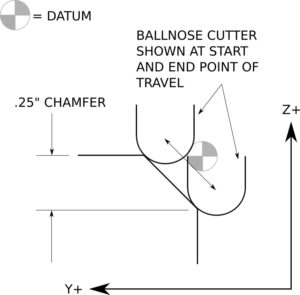
%
OMILL-CHAMFER TRANSLATE
G17 G20 G40 G49 G80 G90
T1 M06 (.25” ballnose cutter)
G00 G54 X-.125 Y.162 S3000 M03
G43 H1 Z1.
G00 Z.1
G01 Z-.037 F50.
M98 P22 L14 (CALLS SUBROUTINE X 14)
G90
G00 Z1.
M05
G91 G28 X0. Y0. Z0.
G90
M30
%
(subroutine)
O22
G91 G01 X.05 F30.
G90 Y-.088 Z-.287
G91 X.05
G90 Y.162 Z-.037
M99 (RETURN TO M98)

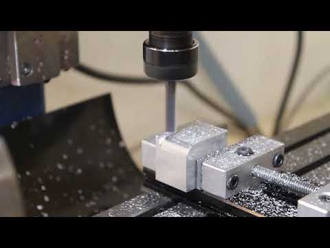
In the video below you can see a demonstration of a G-Code loop creating a chamfer.
I used a slightly modified version of the program shown above, the step over was reduced and the amount of repeats increased.


In this next example I will be doing a .25” radius translated in the Y axis. It is programmed with a .25” ballnose cutter again. You can see from the drawing below that it is programmed to the centerline of the cutter.
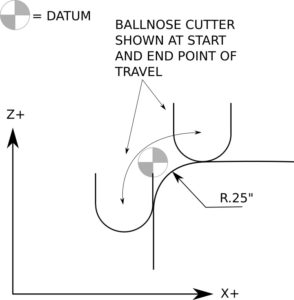
%
OMILL-RADIUS TRANSLATE
G17 G20 G40 G49 G80 G90
T1 M06 (.25” ballnose cutter)
G00 G54 X-.125 Y-.13 S3000 M03
G43 H1 Z1.
G00 Z.1
G01 Z-.375 F50.
M98 P33 L14 (CALLS SUBROUTINE X 14)
G17
G90
G00 Z1.
M05
G91 G28 X0. Y0. Z0.
G90
M30
%
(subroutine)
O33
G18
G91 G01 Y.05 F30.
G90 G03 X.25 Z0. I.375 K0.
G91 G01 Y.05
G90 G02 X-.125 Z-.375 I0. K-.375
M99 (RETURN TO M98)

In the video below you can see a demonstration of a G-Code loop creating a radius.
I used a slightly modified version of the program shown above, the step over was reduced and the amount of repeats increased.

There are currently three other G-Code programming articles on this website, G code programming for dummies, linear interpolation in cnc programming and circular interpolation in cnc, check them out if you want to learn more G code programming.
This article only shows the very basic type of G-Code loops. If you want to advance your skills and understand advanced programming using variables and macros, I can recommend an online course.
Udemy are offering the course ‘Advanced CNC macro programming using G-Code’. Which will take your programming ability to the next level.
If you would prefer to create your programs using Cad Cam software I currently have two articles that demonstrate Fusion 360, Fun Cnc Project and 3D Cnc Machining Tutorial.
G codes
- G00 = rapid movement
- G01 = move at the specified feedrate
- G02 = clockwise arc or circle movement
- G03 = counter clockwise arc or circle movement
- G17 = X Y plane selection
- G20 = coordinates in inches
- G21 = coordinates in MM
- G28 = home position return
- G40 = cutter compensation cancel
- G41 = cutter compensation left
- G42 = cutter compensation right
- G43 = tool length compensation on
- G53 = cancel work offsets
- G54,G55,G56,G57,G58 and G59 = work offsets
- G80 = cancel canned cycle
- G81 = basic drilling canned cycle
- G83 = peck drilling canned cycle
- G90 = absolute programming
- G91 = incremental programming
M codes
- M00 = program stop
- M01 = optional stop
- M03 = spindle on
- M05 = spindle off
- M06 = tool change
- M30 = end of program, rewind and reset
- M97 = subroutine call
- M98 = subprogram call
- M99 = subprogram end


