How to make Wooden Gears on a Cnc Router or Mill
To make involute gear wheels you do not need an expensive cnc gear cutting program. It is quite easy and makes for a fun cnc project!
All you need to do is generate a gear wheel profile and import it into Cad Cam software.
You can find web pages that will generate gear profiles and enable you to download the file in dxf format.
This dxf file can then be imported into cam software to generate G-code for the gear profile that can be used on a cnc router or mill to cut out your gear.
For this tutorial I used the website, gear designer, to generate two gear profiles. One is about 3” in dia, the other around 1.5” in dia. After generating your gear wheel it will let you download it in dxf format.
I had intended to use inkscape software to generate the G-code for the gear wheel but It repeatedly failed with its G-code extension to give me anything usable, so I abandoned that idea.
Instead I opted to use the gear designer website (link above) and fusion 360.
Fusion 360 is a Cad Cam software solution that is available free for hobby users.
It is advanced software that has lots of options and can be intimidating for a newbie, but there are no better (or cheaper!) alternatives.
To create a simple profile toolpath you only need to know a few functions and a step by step workflow, which I will explain.
Create a gear wheel using Fusion 360
- Start a new project in fusion 360
- Insert your gear wheel dxf file
- Extrude the contour profile to create a solid gear
- Select the ‘manufacture’ work space
- Create your setup
- Select the milling strategy
- Input your Z depths etc
- Post Process the tool paths to create your G-code
Using Fusion 360 can be quite an intimidating process for a hobbyist. But, if you really want to be able to create projects to be proud of, learning to use professional grade Cad-cam software is unavoidable.
Taking an online course is the perfect way to get started and I can highly recommend this fusion 360 tutorial for machinists course, check it out!
Although I will hopefully provide you with enough information in this post to produce G-code for your first gear wheel.
I recommend you use wood for your material because it is very forgiving with your tooling and you can mill it at pretty much any feeds and speeds and still get a good result.
Concentrating on just producing a workable G-Code program is easier than having to nail your feeds and speeds to machine a gear wheel in aluminum or steel.
Insert your dxf file into Fusion 360
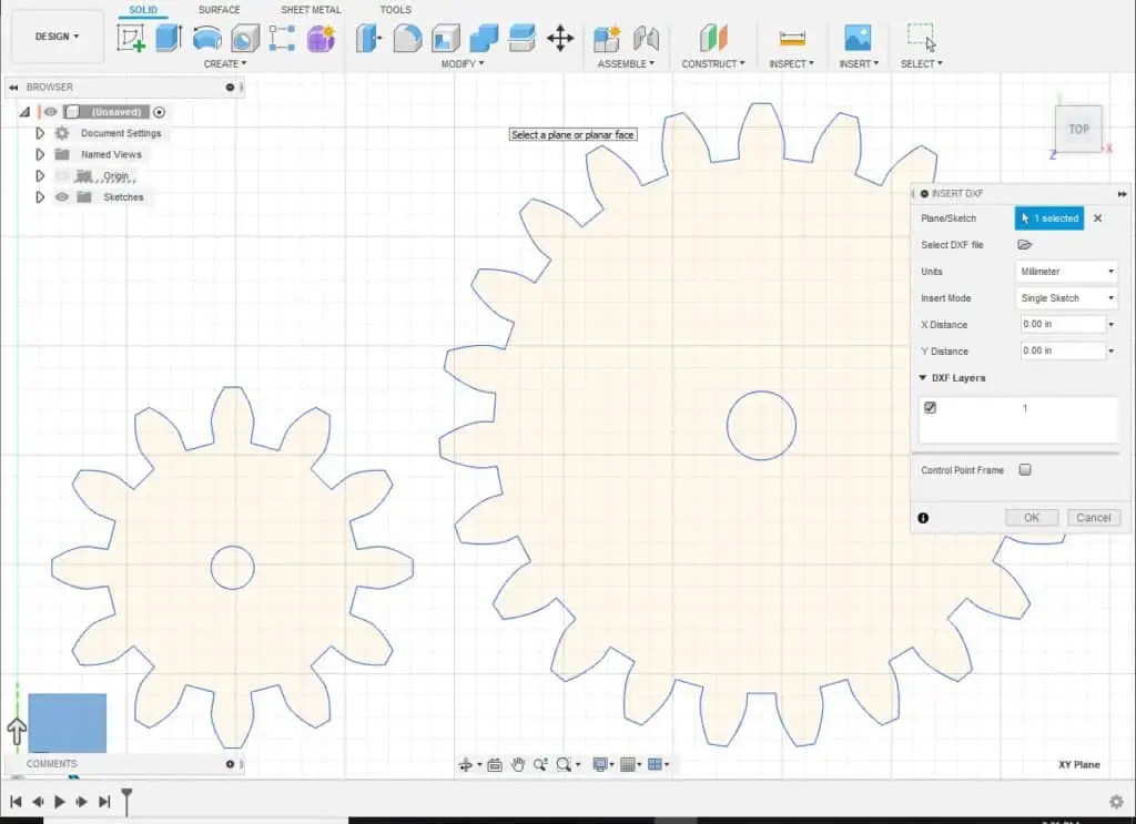
So the first step is to select ‘insert DXF’ from the insert drop down menu.
A box of options will open, click on the folder to locate the DXF file you want to import.
If you downloaded the file or a file from the gear designer website it will be in millimeters, so you have to select millimeters from the units dropdown menu.
You should select millimeters if the cad file was created using millimeters, even if you are working in inches.
Next you have to click on the plane you want the DXF file to be positioned on.
The planes are located at the datum arrows.
Choose the X Y plane, meaning the Z axis will be pointing up or down from your gear profile. You don’t need to change anything else.
Your gear should now appear.
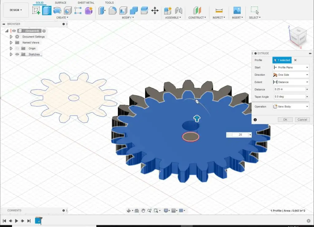
Extrude the gear profile
The next step is to extrude the contour into a solid.
Choose extrude from the top menu, the extrude options will appear, all you have to do is select the profile and type in the height you want your gear wheel to be.
Select the Manufacture workspace
Now you have a gear wheel to mill you have to add tool paths.
Select the top left drop down menu and choose ‘manufacture’.
This takes you to the Cam workspace.

If you look at the top toolbar from left to right, it shows you the process you have to follow.
Starting on the left you have ‘setup’. Click this option first and your setup options box will appear.
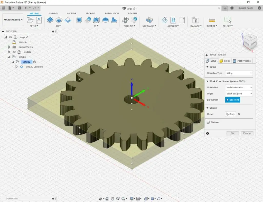
The most important part of the setup process is to indicate the datum position and orientation on your part.
You can click on the head of each arrow on the datum marker to change the orientation of the datum.
The arrows all point to the positive direction of each axis, make sure they have a correct relationship to how the part will be positioned on your machine.
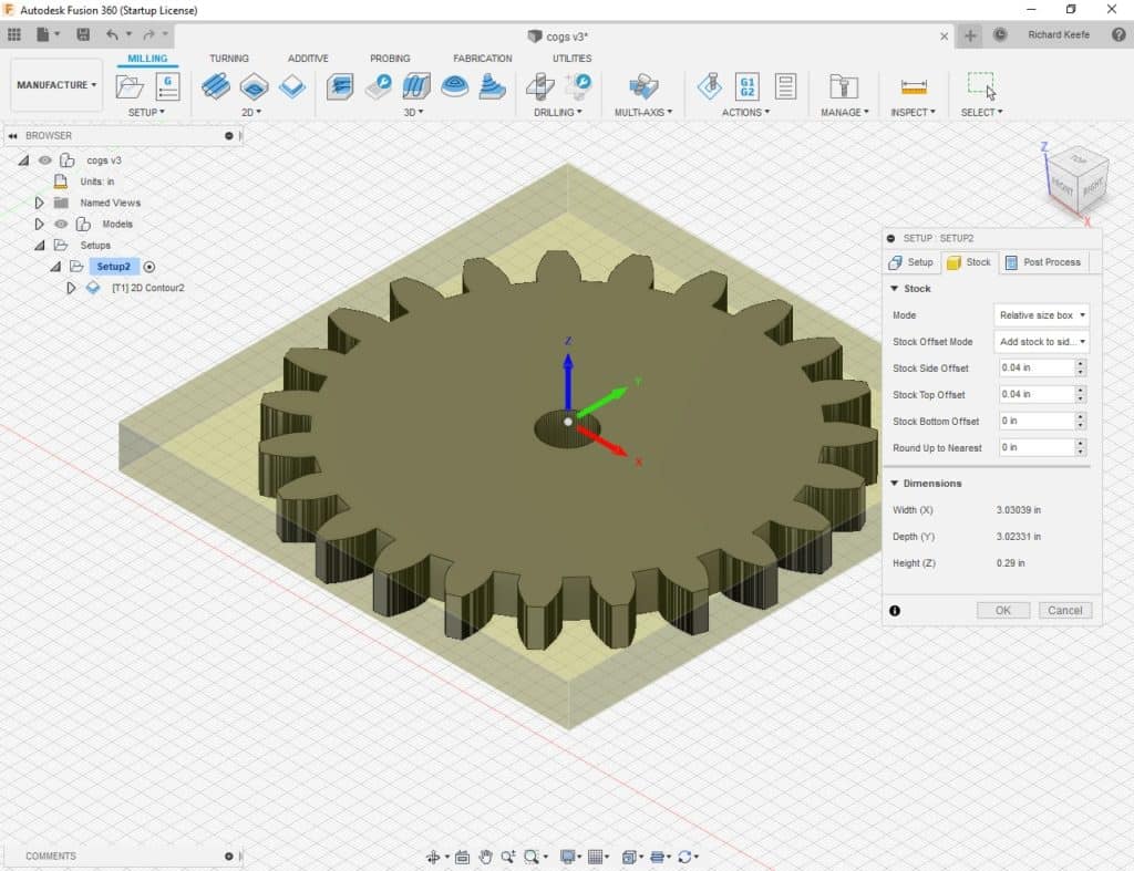
I am only demonstrating a simple contour toolpath so most of the other options can be ignored.
You can go to the post process tab and give your program a name.
Click OK.
Select your Milling Strategy
The next step is to choose your 2D milling strategy.
In this case it is simply 2D Contour.
When the option box opens just go through each section and select each process that you want to use.
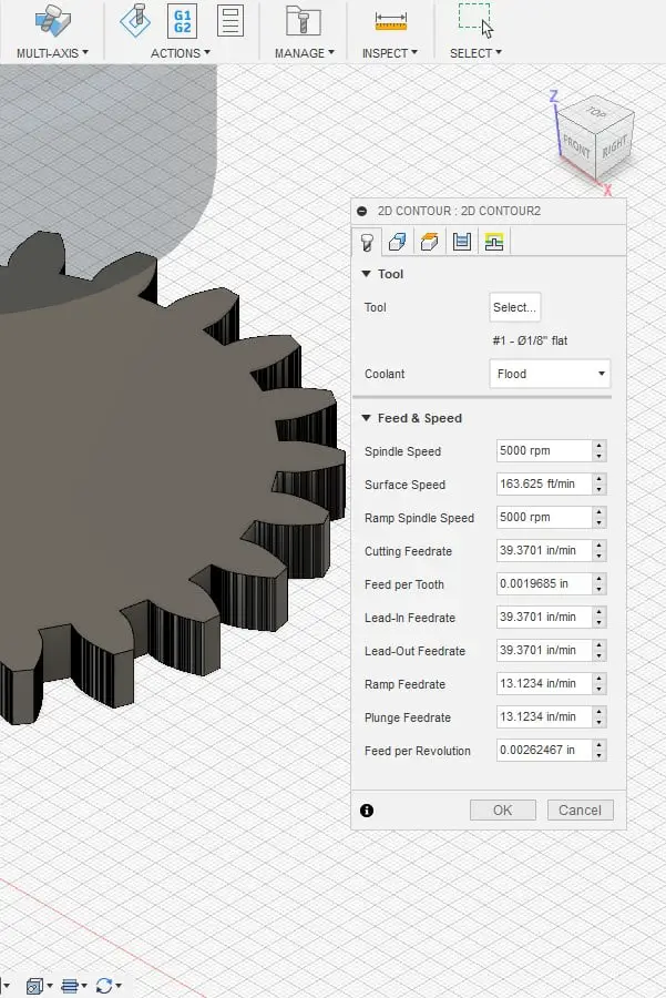
The first choice is to decide which cutter you will use.
The gap between the gear teeth is only small so you need a ⅛” endmill or smaller.
You could do two operations and finish the profile with a smaller cutter to reduce the internal radii later.
I chose a ⅛” endmill. Don’t worry about the speeds and feeds for this project, using wood is very forgiving, just make sure your spindle speed is high.
My machine goes up to 10,000 rpm so that’s what I will run it at.
Fusion will set some recommended speeds, just go with those, they can be changed later.
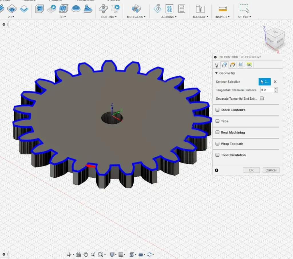
The next tab is the ‘geometry’ tab, use this to select the outside profile of the gear. Ignore every other option on this tab.
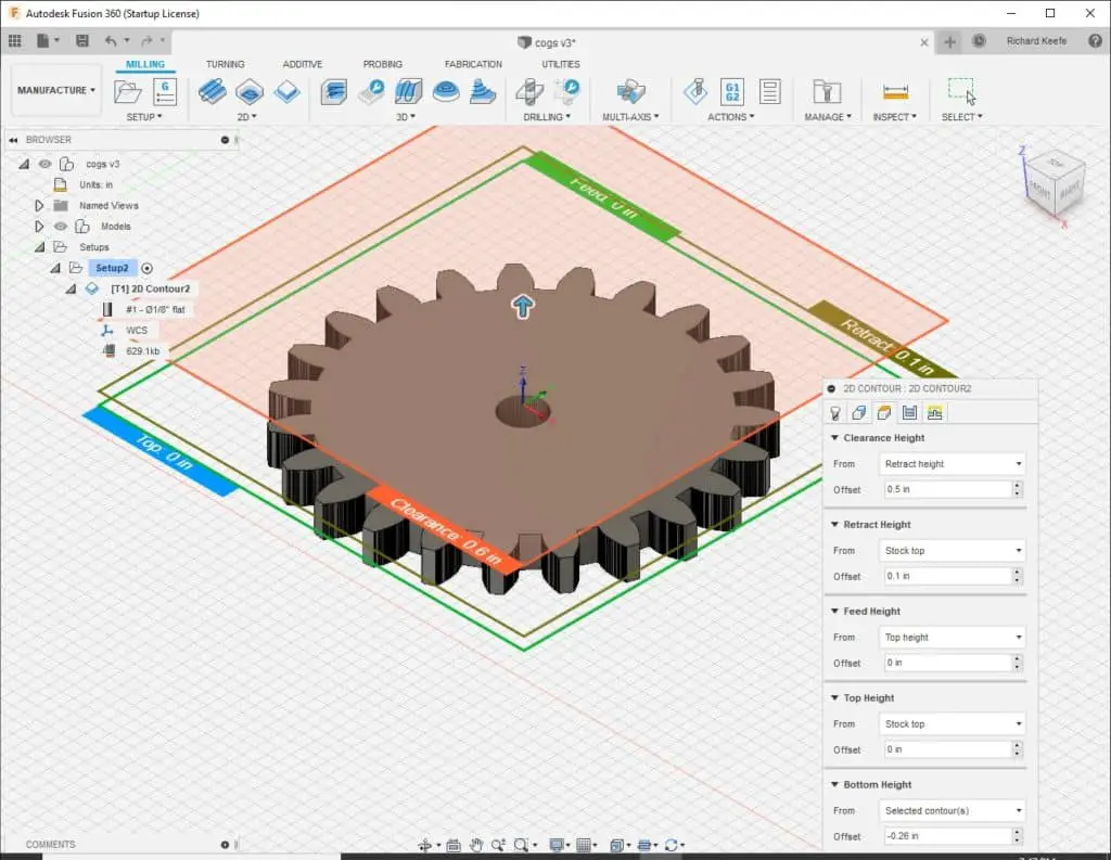
The next tab is the ‘heights tab’.
Go through each option and set them as you need them, they are quite self explanatory.
The critical height being ‘bottom height’, this is the depth the contour will go to.
I will be setting my stock on a wooden fixture plate, so I can go deeper than the thickness of the stock.
My wood is ¼” thick so I have set my depth at -.260”, therefore the cutter will cut .01” into the fixture plate.
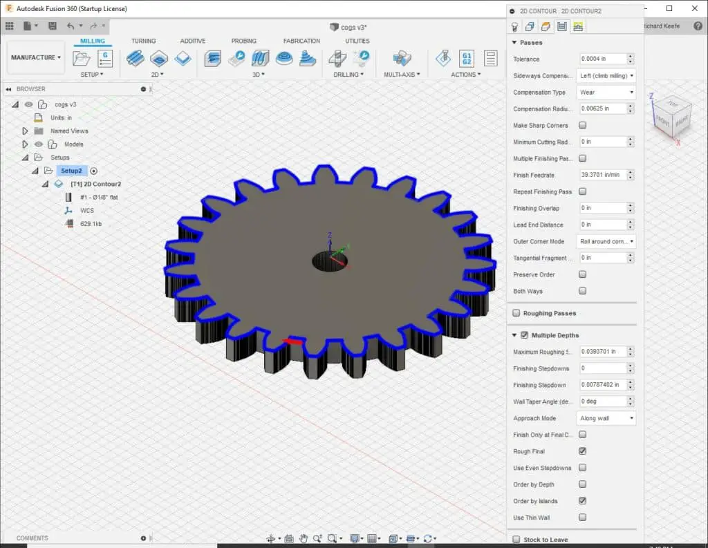
The passes tab is next.
Make sure you have ‘left (climb milling)’ selected, leave the rest as it is in that section of the tab.
Below that is the multiple depths section, select this and decide on a maximum roughing step down. I choose .04”, leave the rest of the options for now.
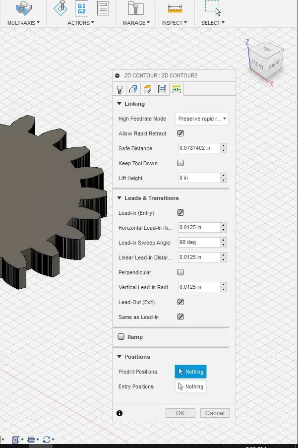
The final tab is ‘linking’.
Just make sure that the ‘leads and transitions’ is selected and leave the sizes as set.
Again these can be adjusted as you get familiar with the software.
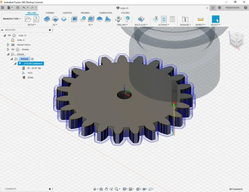
Simulate Toolpaths
Moving along the options at the top of the screen, after all the toolpath options, you will see the simulate button.
Click this and you will be able to run the toolpath you just created.
Check to make sure it does what you want it to do. If not, go back through your settings and figure out what to change or add to get it simulating correctly.
To run your simulation there are buttons at the bottom of the screen to play, stop, fast forward, rewind etc.
Post Processing
Finally we have to post process the tool paths into G-Code.
The post process button is next after the simulate, press it and an option box will open.

Simply choose the units, give the program a name and select a post processor.
If you can’t find a specific post to match your machine I would first try using the Mazak post, this seems to work well for me in Mach3.
You have to use numbers for the name with the Mazak post.

Click ‘post’ and your program will appear in a text editor.
Usually I have to add my header and footer which includes a home position move for all axes. You can find these in my article G28 G-code demystified.
The next step would be to upload the program to your machine control software to check that it reads the post correctly.
Look at it in the tool path display or simulate section and check it looks ok.

Now you know the basics of producing a toolpath in Fusion360 you can go back and add another toolpath using a smaller cutter.
This will reduce the size of the internal rads between the gear teeth.
If you are looking for a quick win and would like to mill a whole collection of spur gears, take a look at my spur gear factory g code.
Now available in the Cnc Philosophy shop!
Making your Gear Wheel
I added a drilled hole in the middle of my gear wheel and made some cutouts just to make it look a little more interesting.
Initially I clamped my wooden fixture plate to the table of my mill and then clamped a blank piece of wood to the fixture.

Once the blank stock is clamped down you can set the datums for the center of the gear wheel.
I just used a pointed tool to set an approximate position near the center of the Y axis movement.
This ensures the program will not hit the limits of the Y axis, as that is the axis with the least amount of travel on my machine.

I first drilled a ¼” hole in the middle.
Then I ran the program I made to add some cut outs.
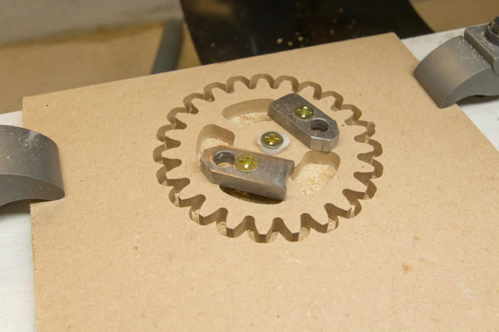
These cutouts served two purposes. It made the gear look more interesting and provided me with access to the fixture board below.

This allowed me to add a couple of clamps to prevent the gear from moving when I cut it out of the surrounding stock.
I also added a screw through the middle hole using a plastic washer to prevent damage to the wood.

Then the main program for the gear wheel was ran.
Make sure your endmill is extended out enough to mill through the wood and clear the top of your clamps.

What next with Fusion 360
Practice using different options in the 2D contour toolpath.
For example, you could add stock for the first pass, then use a finish pass to remove the stock and leave an improved surface finish.
These types of techniques are used consistently when machining metals. Just keep using it and improving your knowledge step by step.
I explain how to do 3D tool paths with fusion 360 in my next post ‘3D machining tutorial‘.
