How to Cnc a 3d model
Any cnc machine that has three or more axes is capable of machining a 3d relief or form.
The only limiting factor is the software you use to generate the toolpaths.
In this post I will be using a free file I downloaded from cults3d.com to demonstrate creating 3D cnc machining toolpaths in Fusion 360.
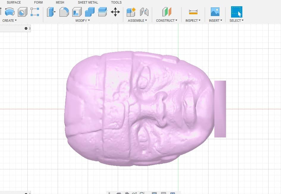
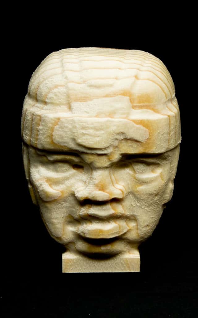
The file is a scan of an OLMEC COLOSSAL HEAD from a museum. I used an stl file which is a 3d cnc file format that can be imported into fusion 360.

Planning your cnc project
The first choice I had to make was what size to make the part. I only have a small cnc machine so I just used a piece of 2X4 wood.
I cut a piece off about 2.8” long, this is small enough to grip in my vise. I now have a size to aim for when importing and scaling the stl file.
The tool paths were created using Fusion 360, a free and powerful Cad Cam software solution for hobbyists.
Open a new project in fusion 360 and choose file>open>open from my computer, and find your file.
Click ‘open’.
Prepare the stl file for machining
Now you will probably have to orientate and scale the model to ‘fit inside’ your stock.
Click the move/copy button on the top menu, when you select the model some grab handles and arrows will appear.
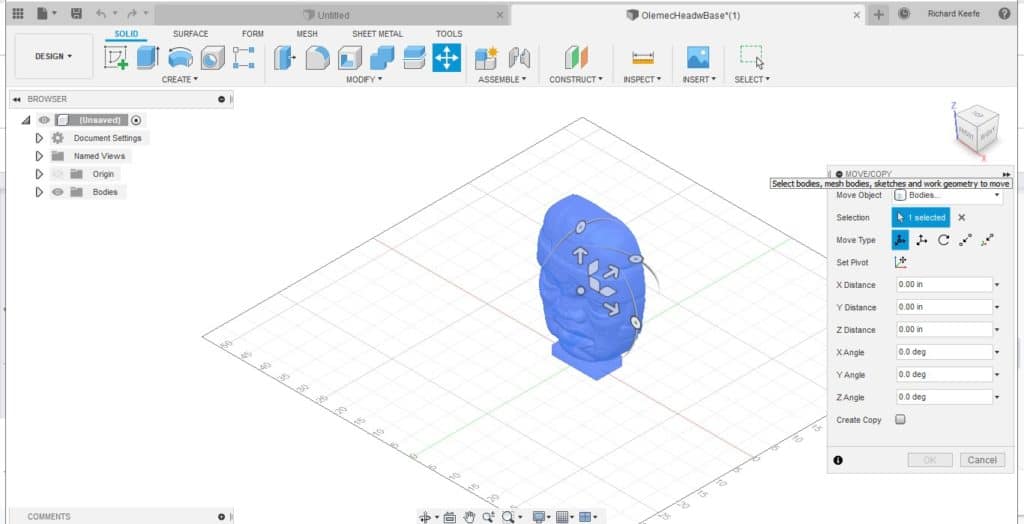
Use your mouse to manipulate the model to the correct orientation and position using the rotation handles and arrows.
Scale the stl file
The next step is to scale the model to fit the size of the stock. Press I on your keyboard and the inspect box will appear.
Select a view that shows you the longest face of the model and measure from edge to edge.
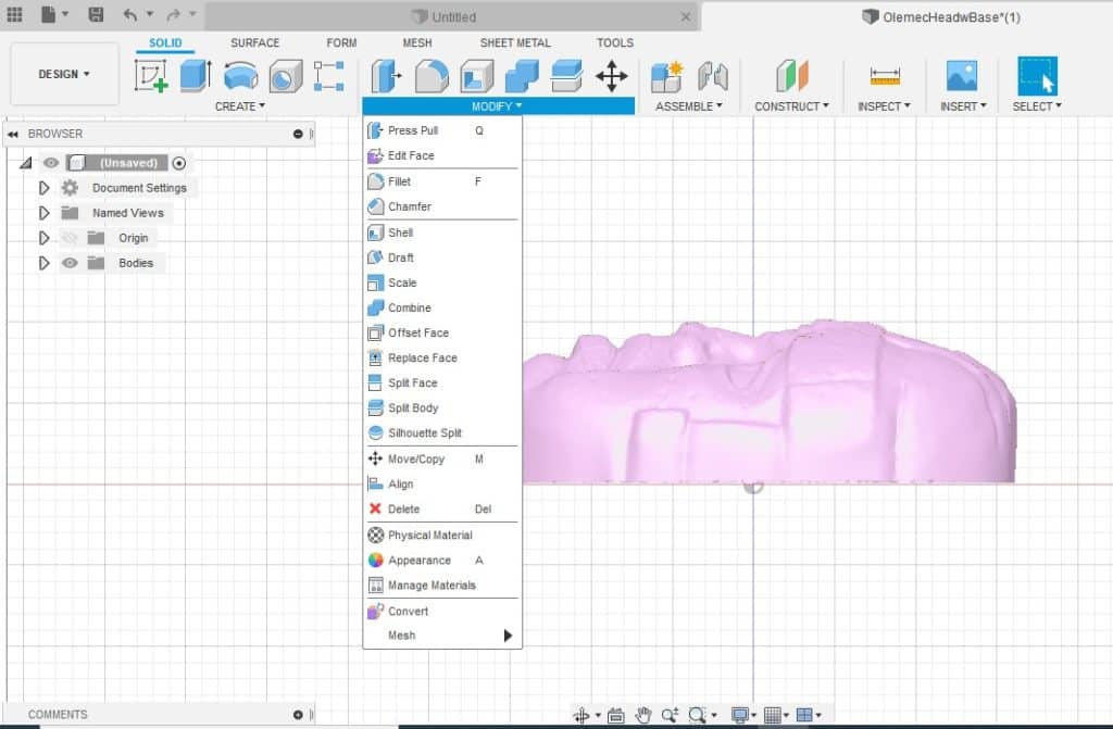
Use this dimension to use the ‘scale’ command to resize the stl model.
Select the modify drop down menu and choose ‘scale’.
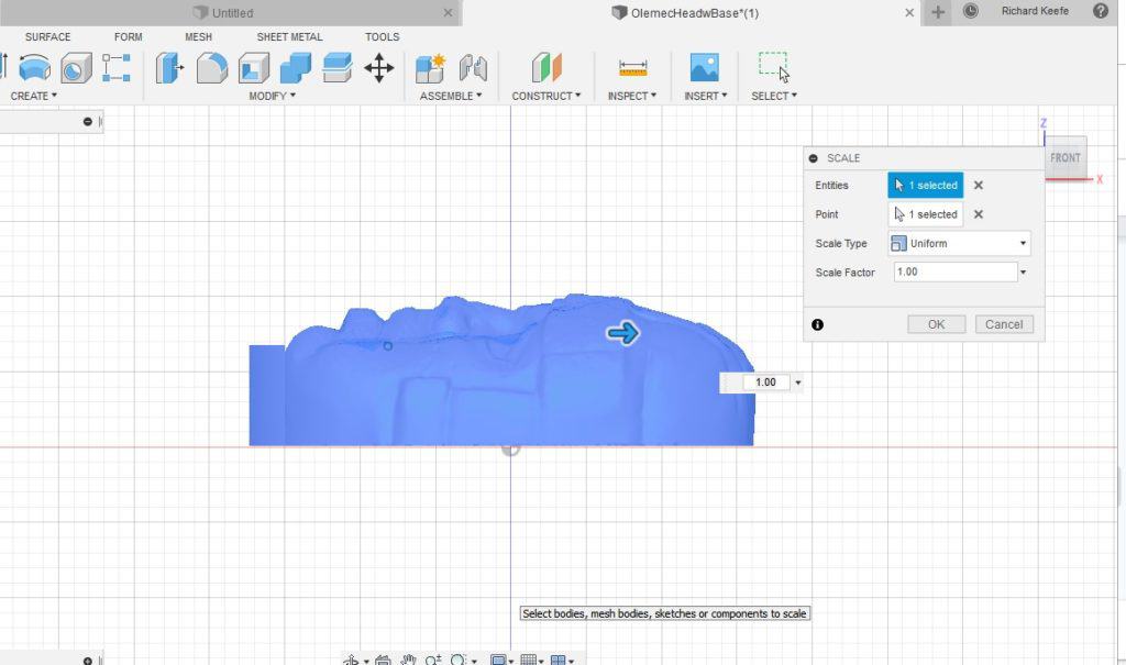
Enter your scale value. Some trial and error may be needed here to get the model to a size that will fit your piece of stock material.
Start the Cam process
Enter the ‘manufacture’ workspace and choose setup from the top menu. A stock box will appear around the model.
Choosing the center of the model for the X and Y axis will probably be the easiest option for a free form 3D model.
Select the top of the stock for your Z axis datum.
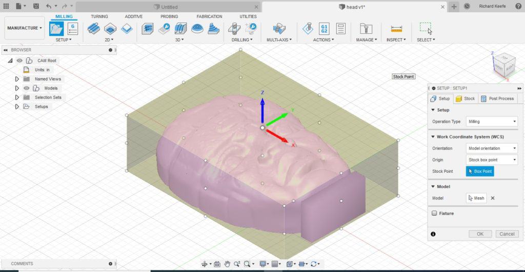
In the stock tab you should adjust the amount of stock to match the physical size of the material you are using.
It only has to be approximate, but it would be preferable to make it slightly bigger than smaller.
Machining Strategy
Now you can start the interesting (fun) part of the Cam process, deciding how to machine the part.
There is not always a set process when deciding on a machining strategy it is highly dependant on the shape of the model.
A lot of trial and error will need to be applied when you are still learning which will reduce to a small amount of testing when you are more familiar with the software.
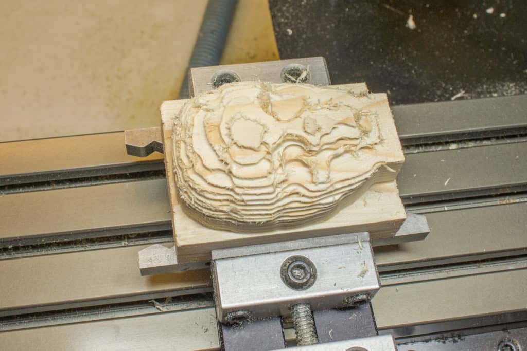
The Roughing Toolpath
This is the easiest choice and usually comes down to 2D adaptive or 3D adaptive clearing.
If your 3D model has a concave area you may have to test the pocket options.
Don’t try and find one strategy to rough the whole part if using two or three works better.
No Cam software is perfect, so don’t try and fight it, sometimes you will have to find a workaround to get the result you need.
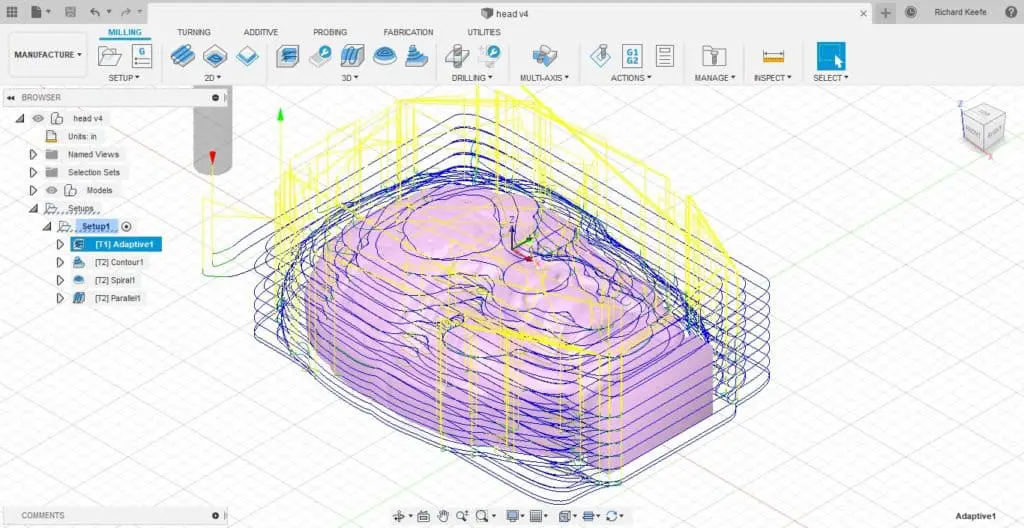
In this situation 3D adaptive clearing works just fine for the model I am using.
Just remember that a smaller depth of cut will remove more material on a model that has a lot of variations in height and surface features.
Again test and try different approaches to see what works best.
Use the Simulate function
When you are trying different strategies remember to use the simulate function to check what the cutter will actually do.
This will help you decide what you need to adjust to get your desired result.
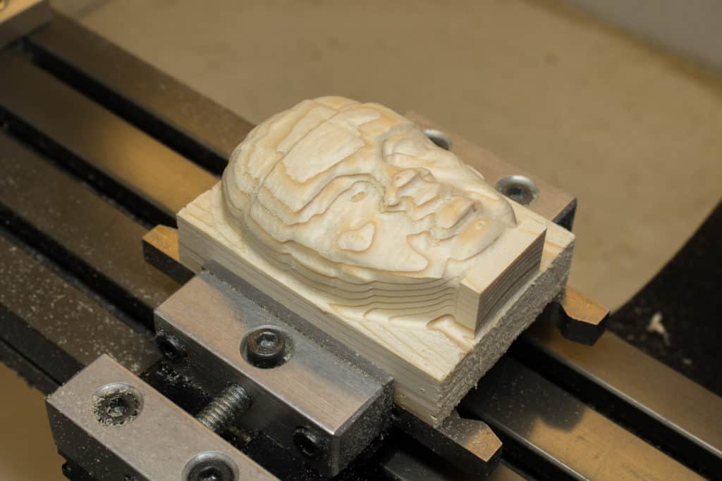
The Finishing Toolpath
Depending on the shape of your 3D model this may be more than one toolpath.
You may also need to do a semi finishing tool path with a larger tool tool first to remove larger areas of remaining stock that were missed in the roughing process.
The ‘rest’ function is designed to solve this sort of issue but is beyond the scope of this article, that’s not to say it’s complicated though. Again, test and try different options, you can’t break a virtual machine!
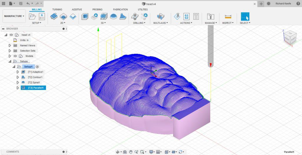
I used three finishing strategies for my statue head.
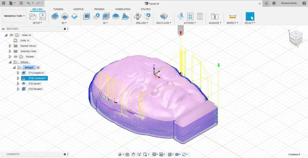
3D contour
This toolpath is ideal for finishing steep walls so I used it to finish the outside of the model first.
Testing is the key to learning, so make adjustments and test.
If you are unsure, the software usually does an ok job of setting values, so you can leave most options as they are.
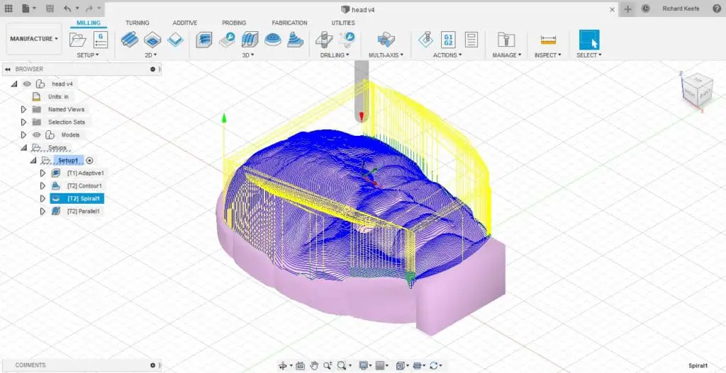
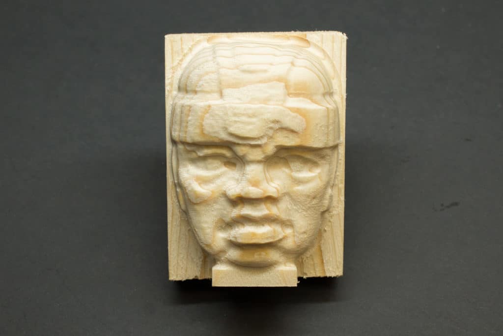
3D Spiral
I chose this toolpath next because it does a good job of creating a smooth finish on a freeform surface. The circular motion works well to cover flat and vertical areas reducing any large step over resolution issues.
3D Parallel
The spiral toolpath did not completely cover the area that the contour toolpath left, so I needed to use a second finishing path to cover the area that it missed. This also had the benefit of improving the surface finish even further.
Post Process the Toolpaths
Once you are happy with your toolpath strategy you can post process them to produce your G-code.
The mazak post processor was used to produce the G-code.
Using Fusion 360 can be quite an intimidating process for a hobbyist. But, if you really want to be able to create projects to be proud of, learning to use professional grade Cad-cam software is unavoidable.
Taking an online fusion 360 course is the perfect way to get started and I can highly recommend fusion 360 tutorial for machinists , check it out!

Cnc Control Software
Once you have your G-code, load it into your g-code software. This should confirm that it posted without any errors. I use Mach3 for my programs.
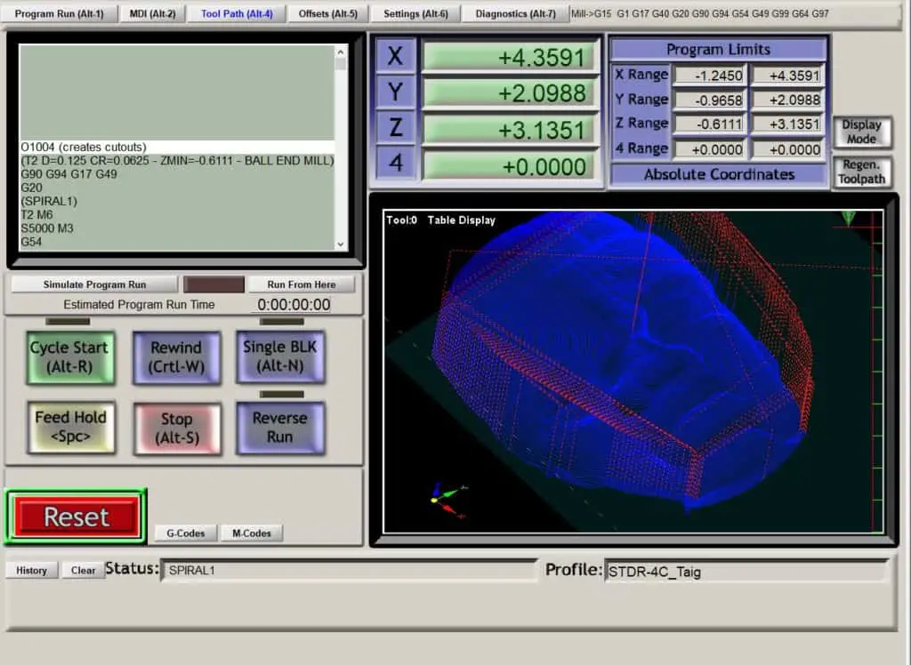
Running Your G-code
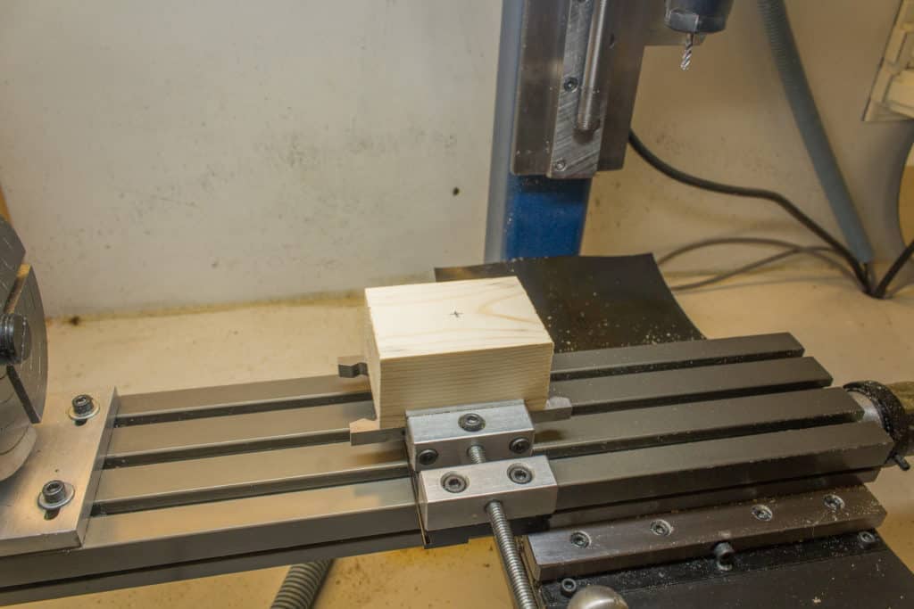
Once the program is ready to run you will need to setup your cnc machine.
How you fixture the stock is important. You don’t want any clamps where the tool will go.
Using a vise eliminates this issue, you just have to make sure the stock is tall enough so that the tools don’t hit the top of the vise jaws. The excess stock can be removed later.
You will also need to extend your cutters out enough to clear the top of the part.
Set your X and Y Axis Datums
For my part, because I had enough excess stock, I only needed to mark the center of the part with pencil lines. I then used a pointed tool to pick up the pencil cross to establish my X and Y axis datums.
The excess stock gave me enough room for error for keeping the finished shape within the piece of rough cut wood I used.
Z Axis Reference Face
An issue you can have when milling a free form 3D file is your Z axis face being milled away with the roughing toolpath.
If you set your Z axis datum on the top of the stock, as soon as you run the roughing pass this reference face will disappear leaving you no way to set the Z datum for your finishing tools.
If you have a machine with an automatic tool changer this wouldn’t be a problem, but most hobby machines don’t, so you will have to plan ahead.
You can use a reference block to set the remaining tools.
All you have to know is the difference in height between the Z datum face and the top of your reference block.
The rest of the tools can be set from the top of the reference block and the Z offset can be manually adjusted in your offset table to account for the difference.
A 1-2-3 block is perfect for this.
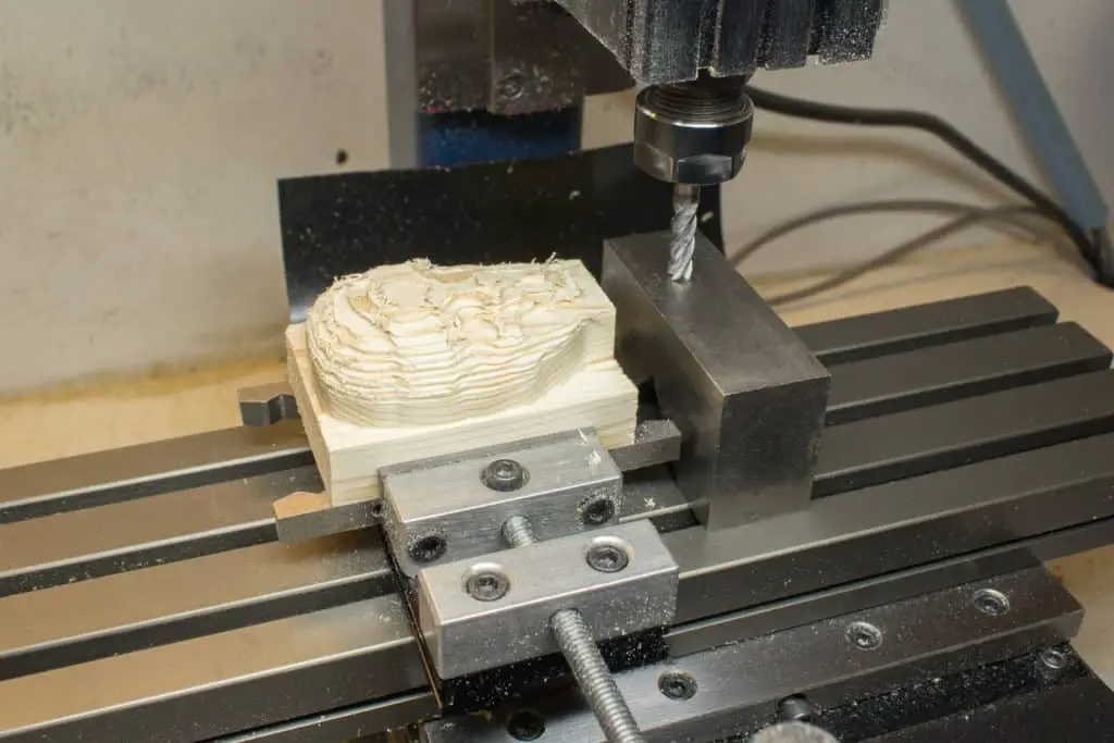
Run Your G-code programs
I posted my G-Code into seperate programs. This is just a personal preference, I just find it more convenient to run them one at a time. It also helps when looking at the toolpaths in Mach3, they are not all layered over each other.
So when you are ready, press that green button…
I have another article about machining an involute gear wheel using fusion 360. This will give you some more insight into creating your toolpaths.


