There are a lot of complex and specialised ways to manufacture spur gears such as hobbing, broaching or grinding.
These types of processes require expensive and complex Cnc Machines, which are out of reach for most hobby machinists, but there is an easier way to produce them.
Simply milling a profile of the gear to cut them out of flat stock.

There are limitations to the size and type of gear you can produce this way but it can be done on a very basic cnc mill.
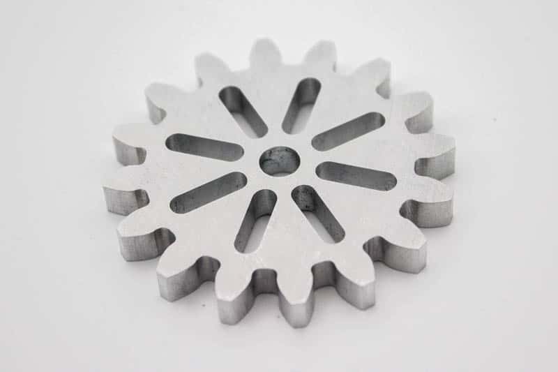
This article will demonstrate a simple way to cut aluminum spur gears on a small desktop cnc hobby mill.
I also made a short video of my Taig mill cutting the gear, you can see this later in the article.
Gear cutting on a vertical milling machine
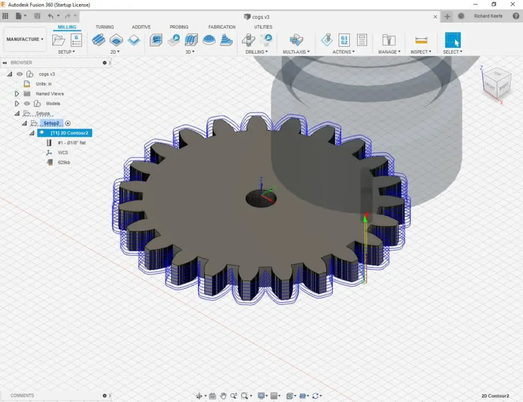
An overview of the process for generating the 3D file to create the tool paths are as follows:-
- Generate a spur gear profile using an online resource, e.g. gear designer
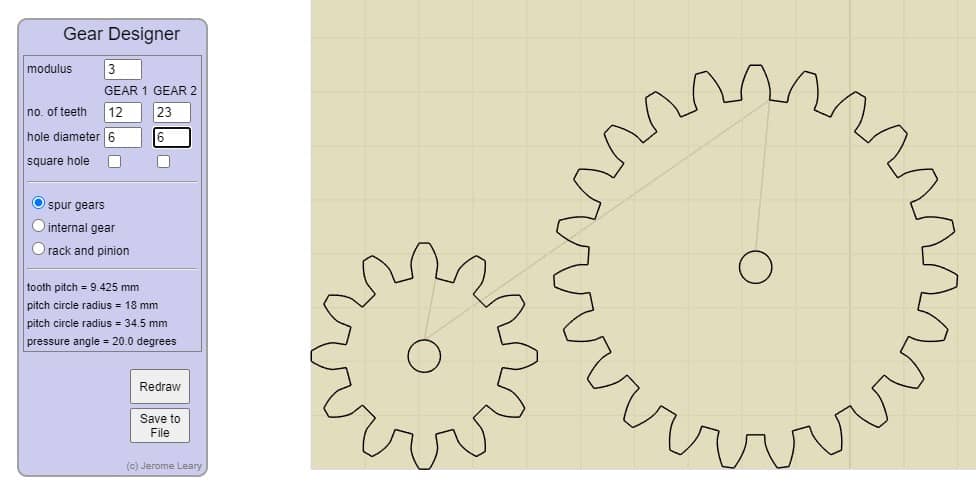
- Use this software to dictate the size and number of teeth etc

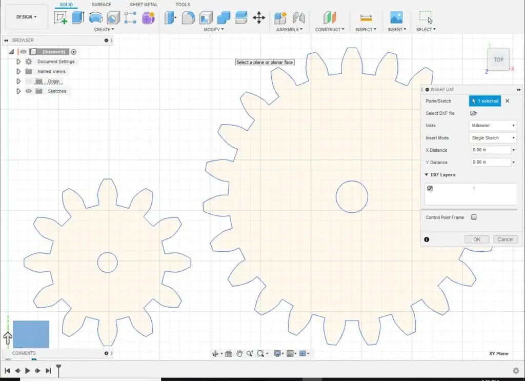
- Extrude the profile to create a solid 3D file and add a center hole etc
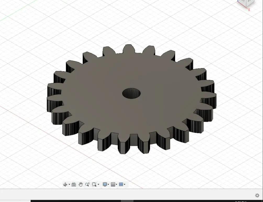
- Create your tool paths from the solid model
I explain and demonstrate this process in more detail in my ‘fun cnc project’ article if you want to create your own gears using the method shown above.
For this example I used some G Code programs I have already created for my Spur Gear Factory download. (A full set of G Codes for 8 spur gears are available in my Store.)
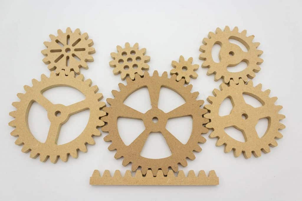
I originally made these files to run on a basic 3018 engraving machine and to be made from wood.
Wood being the only material the 3018 engraving machine can mill effectively.
To make this spur gear from aluminum I used my Taig cnc mill. It is a lot more capable than the 3018 engraver and is designed just like a ‘full size’ milling machine, except shrunken down to fit on a bench.

This machine runs using Mach3 software which has no issues running these programs even though they were created using a Grbl post processor.

Also, no changes were made to the Spur Gear factory G Code files to mill the gear in aluminum, they were run ‘off the shelf’.
The only differences between milling the wooden gear and the aluminum gear were the machine I ran them on and the cutters I used. I didn’t even have to alter the cutting speed.

End Mills for aluminum
As mentioned above, the other change I had to make from running the spur gear G Code in wood to milling in aluminum was my choice of cutting tools.
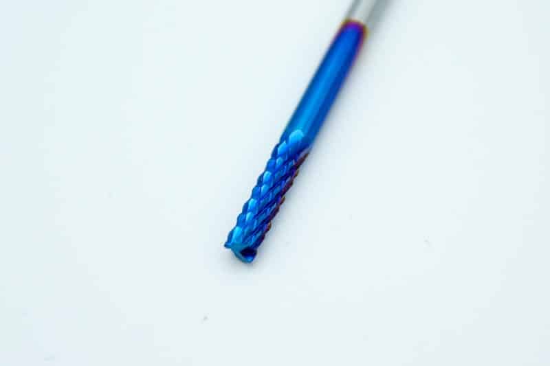
On the 3018 engraver I used the Genumitsu ‘burr’ style of end mill, these are fine in wood but they are useless for aluminum.
My Spur Gear Factory download programs make use of a 1/8” end mill and a 5/64” end mill. I already had a 1/8 “ carbide slot mill but I needed to buy a 5/64” end mill, so I bought a set from Amazon. It was the ideal opportunity to test a ‘proper’ set of carbide end mills that are readily available to buy. (A good price too)
[amazon box=”B07D6J5PQY” price=”hide”]
This set of 5 end mills are metric, they include a 2mm, 3mm, 4mm, 5mm and 6mm. I needed the 2mm which is very close in diameter to 5/64”. (less than .001” difference).
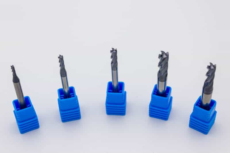
The shank is 4mm in diameter which is very close to 5/32”, so it fits nicely in my 5/32” ER16 collet.
The larger end mills have a 6mm shank which can be used in a ¼” ER16 collet.

I have only used the 2mm end mill so far, but it works as expected and produced a very good finish.
All five of the end mills have been ground correctly and have the look and feel of similar quality end mills I use at work.
Highly recommended, and they were the least expensive set that was available.
How do you cut gears on a milling machine?
The general workflow process I used to mill the gear is as follows:-
I repurposed an old cpu heatsink for my gear blank, sawing off the fins and facing it down to .236” (6mm) thick.
This thickness suited the programs that I had already written for the Spur Gear factory G code.
I sat the part on a small piece of wood so I didn’t cut into the table when I cut through the stock. This was held down with a couple of clamps positioned near the edges of the stock so as not to interfere with the cutting process.

The X and Y datums were set approximately in the center of the stock using a pencil mark as a guide. Accuracy positioning the center datum position was not a priority because the overall size of the stock was big enough to cover a small amount of misalignment.
The Z datum however was set accurately using a piece of paper between the end mill and the top of the blank stock. Use the manual step function to lower the tool in .001″ increments until it ‘grabs’ the paper.
This will indicate the end mill is about .003″ above the stock. The Z datum can now be set accurately.
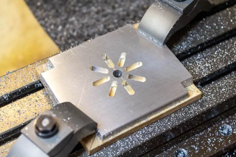
The first three programs for the 16 tooth spur gear are for the detail in the center of the gear.

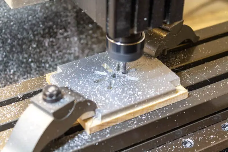
The center hole and the slots were milled first, then the center of the gear needed to be clamped down.
Once the center of the gear was clamped down through the center hole, the outer profile programs were run. These cut out the gear profile and then reduce the corner radii with the 5/64” (2mm) cutter.
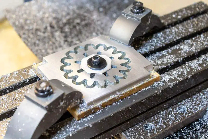
I used a thin piece of aluminum as an extra washer to spread the load when bolting through the center hole to the T-slot nut under the part. It also prevented the steel washer above it from marking the softer aluminum.