Fusion 360 Basics
This is the first in a series of Fusion 360 training articles dedicated to teaching the basics of Fusion 360.
This article will show you a step by step process for producing your own G Code using Fusion 360.
This introduction is titled ‘Fusion 360 basics’ because you don’t have to learn everything about this software to use it for creating your toolpaths. You will only have to understand a few of Fusion 360’s capabilities to get creating your projects.
The emphasis on this tutorial and any I do after this will be on creating toolpaths for a cnc machine. The majority of the tutorials I have seen neglect this area and concentrate on the design aspect only.
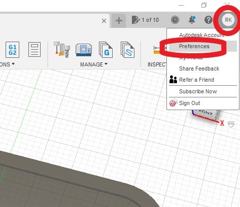
If you want to find Autodesk’s knowledge base just click the ‘?’ in the top right hand corner of the Fusion 360 user interface.
How hard is fusion 360 to learn?
This is an open ended question, but to just get you started I am going to demonstrate in this article the minimum amount of knowledge needed to create basic toolpaths.
In my opinion the effort involved in learning Fusion 360 is well worth it because it is very capable and it’s free.
The best way to learn Fusion 360 is to dive in and try it.
Fusion 360 User Interface
If you have used a CAD program before, a lot of the buttons and the layout in general should be quite familiar. I will briefly explain the basic functions, specifically the ones I will be using in this tutorial.
Fusion 360 View Cube
In the top right corner is the ‘view cube’, this is used to position your view point to the workspace and your work. You can click each area of the cube to reposition your view point in relation to workspace and your design.
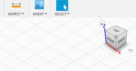
It is also possible to ‘grab’ the cube with your mouse and rotate it around. To reset your position just click the ‘home’ icon next to the cube.
Workspace Menu
Fusion 360’s multiple workspace environments are quite unique when compared to other cad/cam programs. Fortunately as machinists we only have to concern ourselves with two of them, Design and Manufacture.
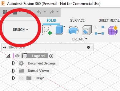
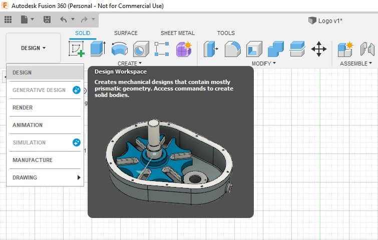
Design
Design is the first workspace you will use to create the shape or component you want to make on your cnc mill.
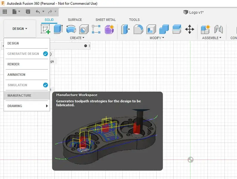
Manufacture
Once you have created your design all you do is select the Manufacture workspace from the drop down menu and the menu bar will change to show all of the toolpath options.
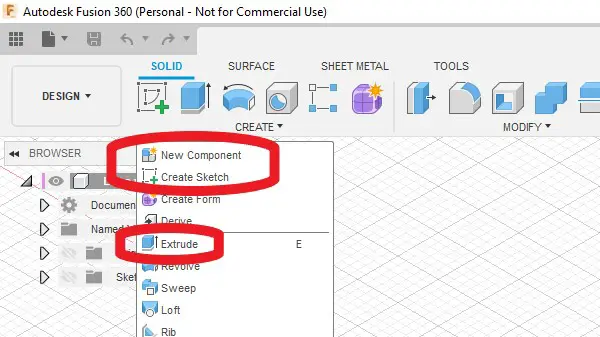
The Create Dropdown menu
There will be 3 functions we will use from the Design Workspace menu.
- New Component
- Create Sketch
- Extrude
New Component
This is Fusion 360’s answer to layers. Creating separate components will enable you to hide and display multiple parts of your design. This allows you to ‘declutter’ your workspace when working on a particular area of a design assembly.
This is not really needed for what I am going to show you in this tutorial but it is a very easy process to do and if you get into the habit of doing this now you will benefit when you get more ambitious.
Using this feature will enable you to create multiple designs in a single document. This is important when using the free version of Fusion 360, which has limited project ‘saves’.
Create Sketch
Creating a sketch is the first process in most designs. A 2D sketch, basically a flat drawing, is made, which can then be extruded into a 3D shape. This 3D shape can then be refined further, new sketches can be added onto faces of this 3D object, which can then be extruded to add further features.
Extrude
This function is used to extrude your sketches into a 3D body. It’s super simple to use.
The Sketch Dropdown Menu
Starting a new sketch will change the menu bar options across the top to reflect the sketch options.
I will only need to demonstrate 2 options from this menu, these are rectangle and fillet.
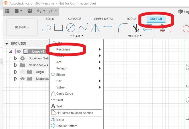
Fusion 360 Rectangle function
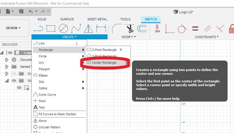
The create rectangle function gives you 3 different ways to create a rectangle.
- 2 point rectangle
- 3 point rectangle
- Center Rectangle
I will be demonstrating the Center Rectangle option
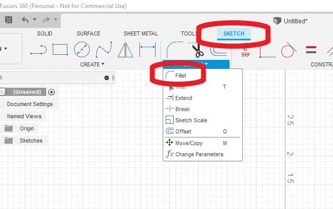
Fusion 360 Fillet Command
The Fillet command is in the sketch modify menu. This function will be adding corner rads to the rectangle.
Creating a Simple Design in Fusion 360
The first task you should do is to create a project folder (before you have done anything) and give it a name.
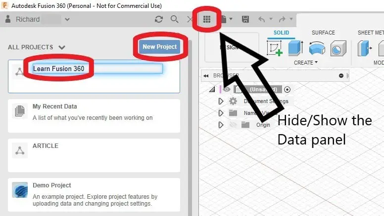
Click the Data Panel and open a new project, give it a name and then double click it. I called my folder ‘learn fusion 360’.
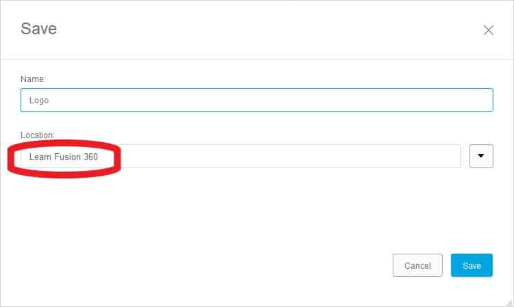
Hide the data Panel, press the save icon, give your current file a name (again before you have done anything) and choose the project folder you just created.
If you want to know where Fusion 360 stores your files, read this article.
Units of Measurement
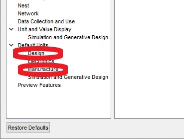
If this is your very first time using Fusion 360 you will need to set your prefered Units. Simply pull up your preferences popup box and change the default units in the ‘design’ and ‘manufacture’ sections.
Create a New Component
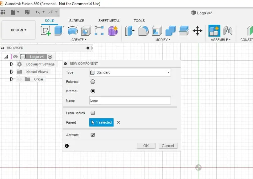
Click Create>New Component.
A new component box will open, give it a name, I called mine ‘Logo’.
Your component will now be added to the ‘browser tree’ on the left of the user Interface.
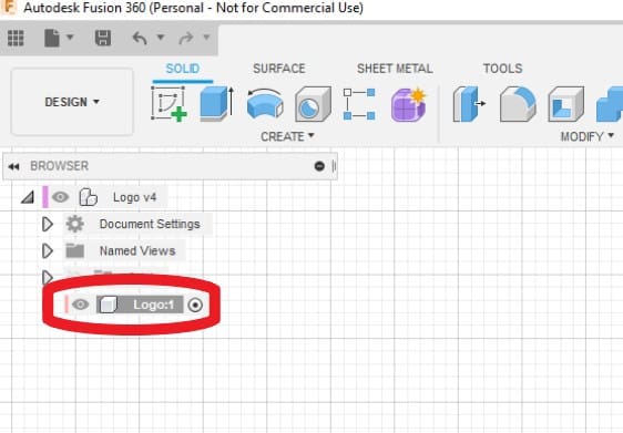
The dot next to the name indicates that it is currently active. If you have multiple components you can switch them on or off by clicking the dot after the name.
Create a Sketch
Let’s do this!
Hit the create a sketch button, you can find it in the dropdown menu as shown before or just click the icon in the main menu bar.
The first task is to select which plane you want to draw your sketch on. Being machinists I recommend hitting the top view in the view cube and selecting the X Y plane.
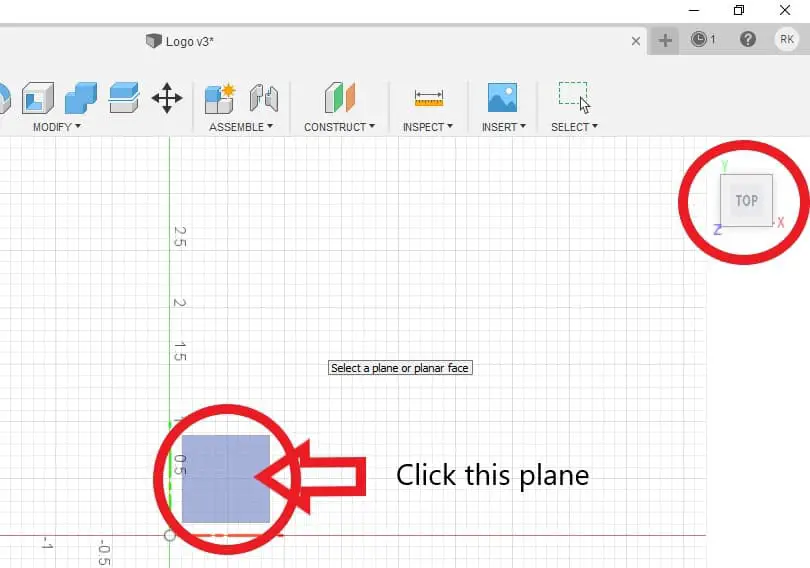
You could choose any plane, your part can be re-orientated and a new Datum position selected in the Manufacture workspace but it helps to keep things simple
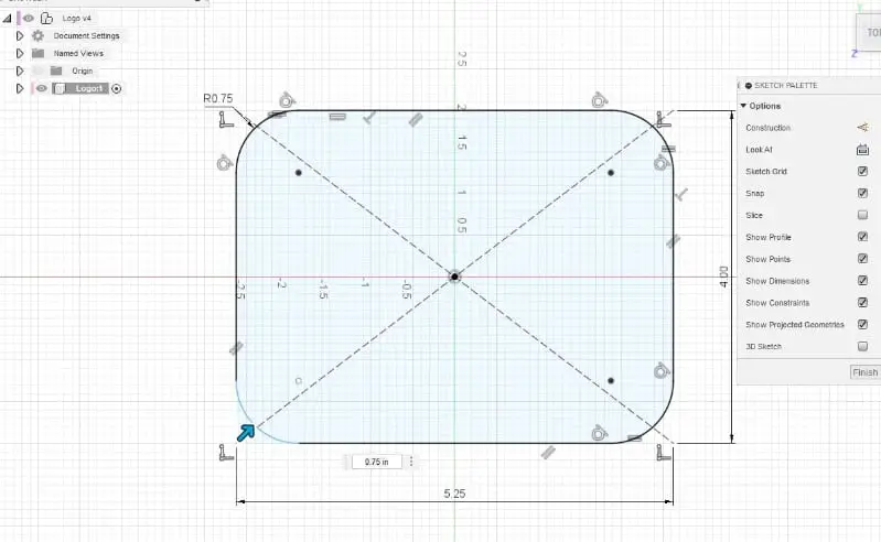
Create a Rectangle
Choose the center rectangle from the menu.
Click on the X Y zero center in the workspace and drag your rectangle out. Your mouse should ‘snap’ to the datum icon on your workspace.
As you drag the rectangle you will notice two dimension values, one of them highlighted in blue.
You can now type in the dimension you want the height to be, don’t press enter yet, press the tab button and the second dimension will be highlighted. Go ahead and type the length dimension.
Press enter.
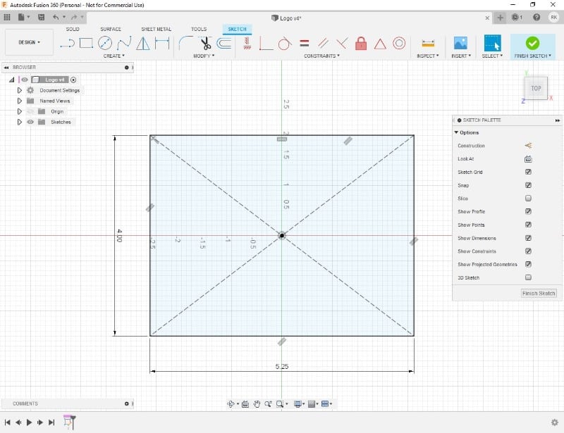
These dimensions can be changed after by double clicking the values and entering a new value.
The Fusion Sketch Fillet Command
Now I am going to add rads to the corners of the rectangle.
Go to Modify>Fillet.
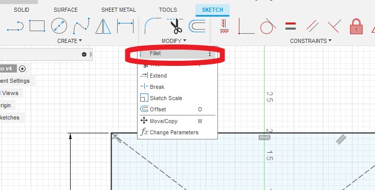
Now all you do is select two adjoining lines and a fillet rad will be added to the corner.
Type in your required size in the dimension box.
Don’t press enter until you have done all 4 corners.
Now that I have done the outline to my project I can finish the sketch. This will exit out of the sketch environment ready for the steps.
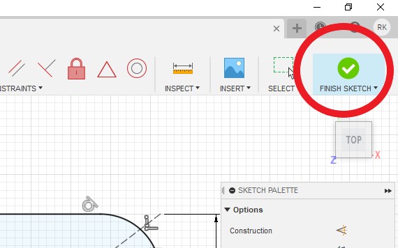
If you exited out of the sketch environment too early and you need to add an extra feature for example, don’t start a new sketch.
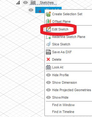
Click the little arrow next to the sketches folder to show all sketches in this component.
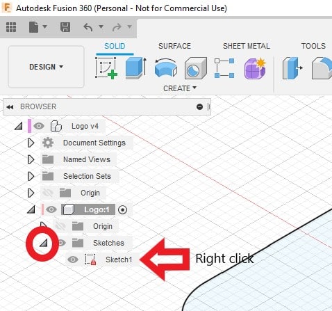
To go back into a finished sketch to re-edit it, right click on the sketch in the browser tree.
Extrude
Now you can turn the sketch into a solid object. Click the extrude icon or the Create>extrude menu. Type in a distance in the dimension box for how far you want to extrude your sketch.
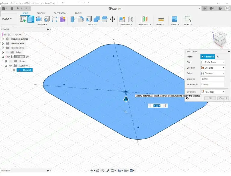
You can also drag the arrow with your mouse.
Use a negative or positive dimension to control the direction of the extrude.
I want to add a raised border to my sign, to do this I will start a new sketch. This time, when prompted to select a plane to draw my sketch on, I will select the face on my extruded rectangle that I want to add my border on.
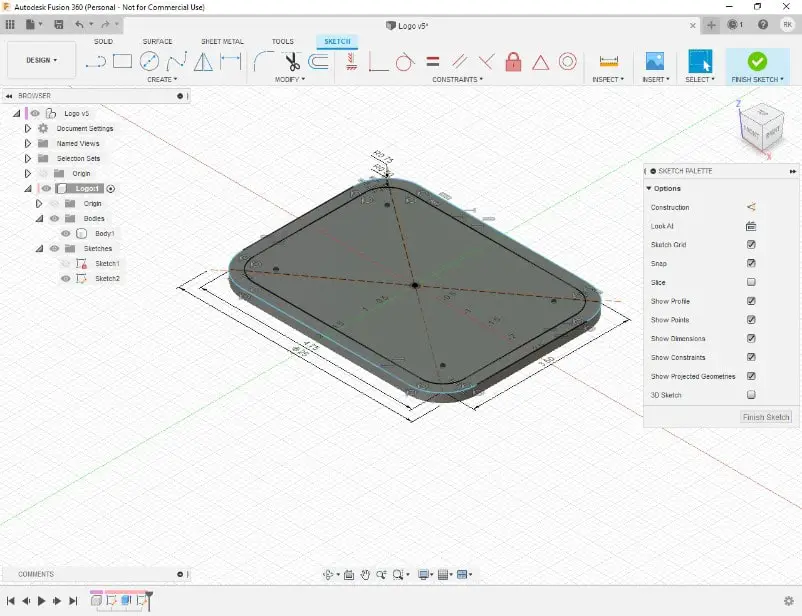
Initially I sketch another rectangle the same size as the previous one plus another which is 0.5” smaller on the inside.
These two rectangles will be used for a border.
Then I just repeat the previous process to extrude this sketch.
Finish the sketch and hit the Extrude Icon again. This time highlight the area between the two new rectangles and type your distance to extrude in the dimension box.
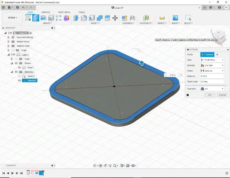
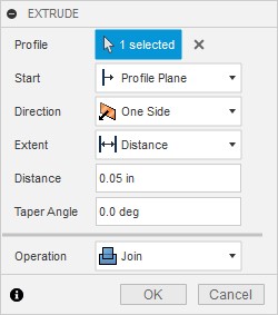
An important note here is make sure you have ‘join’ active in the extrude option box. This will add the extrusion to the current body and not create a separate body.
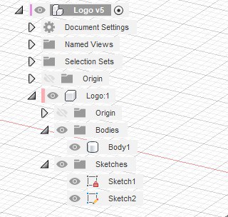
If you look at the browser tree you will see that I have 1 body and 2 sketches. You can click the ‘eye’ icon to make them visible or hide them.
Insert an SVG File
Now I have the ‘frame’ of my sign, I am going to show you how to import and use an SVG file.
This is useful to know because you can create lettering with any variation of fonts in design software like adobe Illustrator or Inkscape.
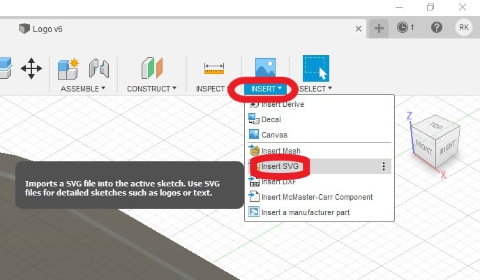
Click on Insert>insert SVG.
You will be presented with a pop up window letting you browse Fusions Project folders or you can insert from your computer.
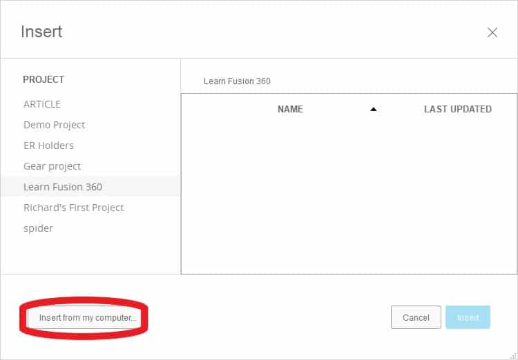
Find your file and select it.
You will then be asked to select a plane onto which you want the SVG inserting.
Select the center surface of the frame.
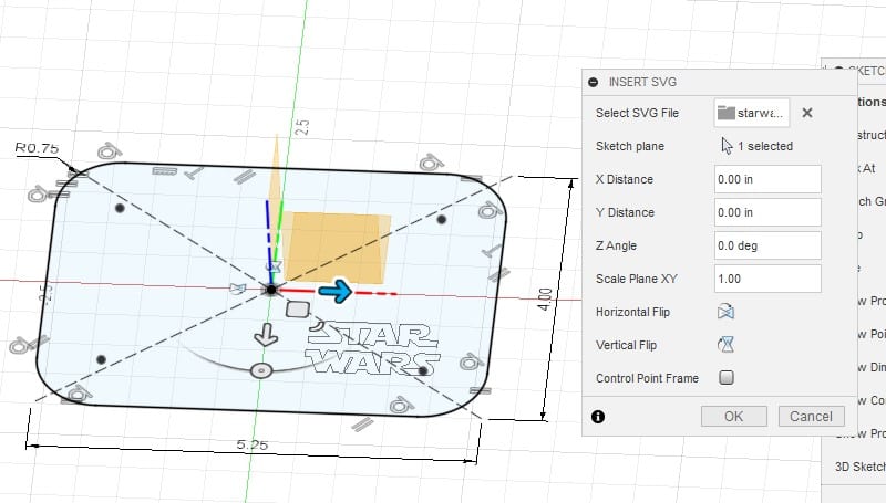
Your SVG file should now be positioned somewhere on the selected surface.
The pop up box will allow you to position and scale it to fit the frame.
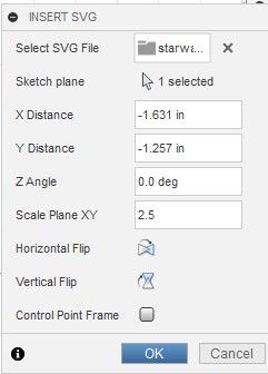
You have two choices here, you can manually manipulate the ‘handles’ to position the SVG or you can type in the pop up box how far to move it.
I prefer to use the handles to move and rotate the SVG.
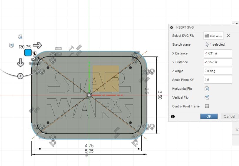
Note, It is easier to scale your logo first, then reposition it.
When you import an SVG, Fusion turns it into a sketch, so now you can extrude your logo/lettering to give it a physical dimension.
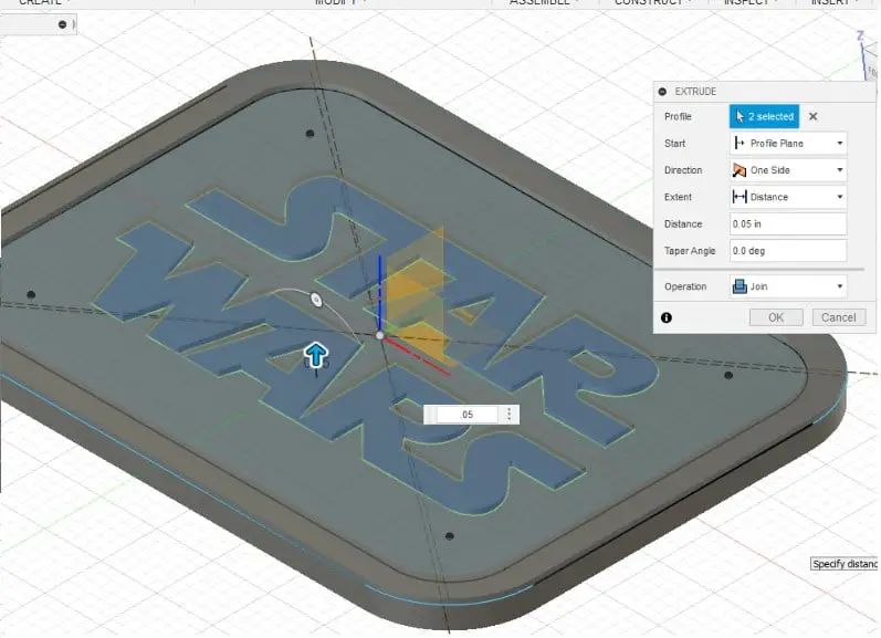
Note, To extrude your lettering/design it has to be a closed ‘circuit’ with no open ends.
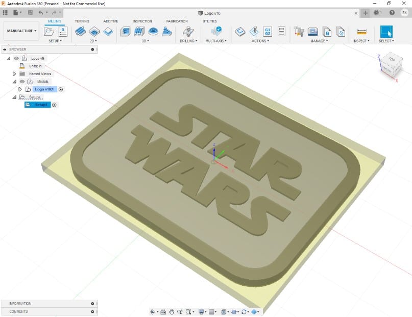
Fusion 360 Cam Tutorial
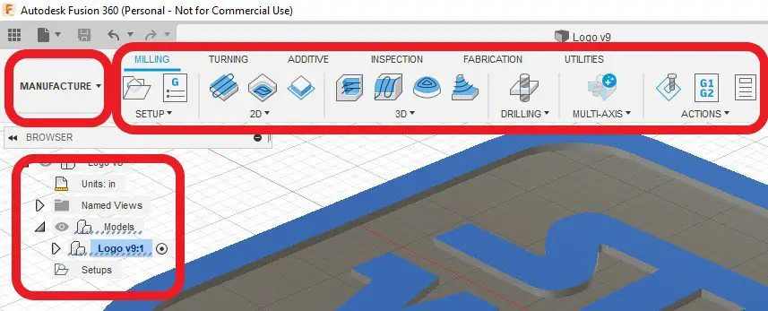
Now we have a design to work with, you can move to the Fusion 360 Manufacture Workspace.
Once in the Manufacture Workspace you will notice the browser tree on the left of the screen has changed and the menu bar across the top has changed.
New Setup
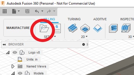
The first task you have to do when making toolpaths is to create a new setup.
Click the new setup icon in the top menu bar.
A popup menu will appear with 3 tabs for you to go through, Setup, Stock and Post process.
Setup Tab
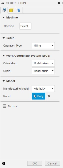
Machine
You can leave this alone, it isn’t needed.
Setup
Set this to milling, this should be the default option.
Work Coordinate System (WCS)
Orientation
If you created your design in the correct orientation for your mill you can leave this as ‘model orientation’. If not, choose an option to set the design to the correct orientation.
Origin
This is where you decide the position of the X Y and Z axis zero datum point.
If you created your design with the datum where you wanted it you can choose ‘model origin’.
If you need to move it I usually choose ‘model box point’. This will put small white dots at various points on your model, just choose one.
I almost always choose the center dot at the top of the part.
(click the mouse arrow icon box to select your dot)
Model
If you are working with more than one solid body you can select which one(s) to work with. You have only one body so it defaults to that. So leave this alone.
Stock Tab
This is where you tell Fusion 360 what the size of your stock is. Inputting the correct size will show you how your part will get machined when you simulate your toolpaths, so input the sizes as accurately as possible.
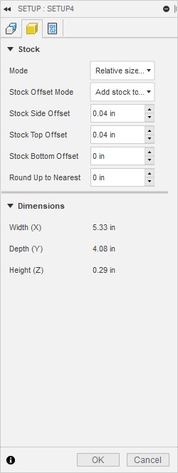
In the Mode drop down menu select “fixed size box’.
Then just type in the dimensions of your stock.
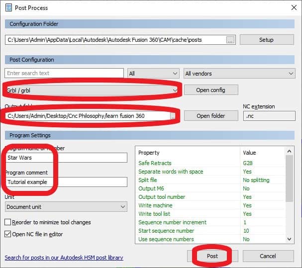
Post Process Tab
You can type in a name (or number) for your G Code file here and add a comment if you want.
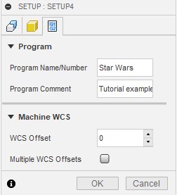
Don’t worry about the Machine WCS, it won’t affect anything to just leave this.
Now you can click ‘OK’ and your setup is complete. You can make changes anytime you want by double clicking the setup folder in the browser tree. This will bring you ‘setup’ popup back up.
Fusion 360 Toolpaths
Now the fun part!
Moving along the top menu bar is the ‘2D dropdown menu.
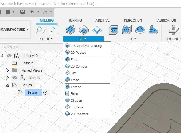
We will only be using 2 toolpath strategies in this tutorial, both of them from the 2D menu.
2D Contour
For this first toolpath I will show you how to cut the outside profile.
Select 2D contour from the drop down menu.
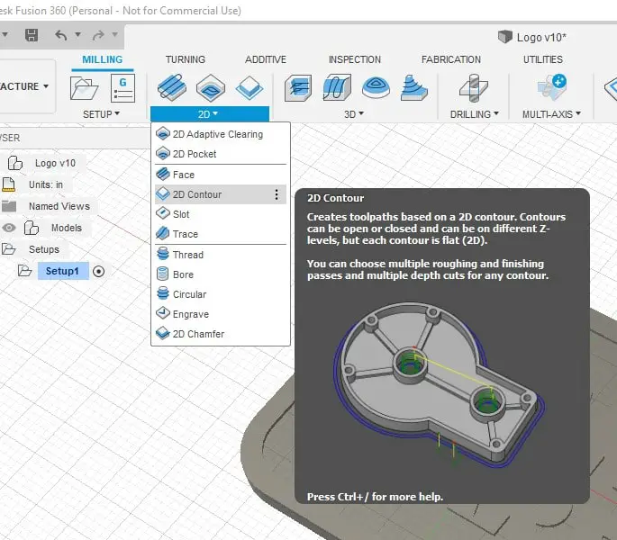
This will bring up a popup box that has 5 tabs.
- Tool
- Geometry
- Heights
- Passes
- Linking
There is a lot of information needed here, but a lot of the values are already filled in.
For the sake of keeping things simple I will only show the minimum needed to get a toolpath, once you get more familiar with each process it will get easier.
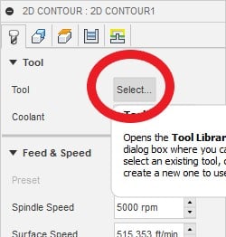
Tool Tab
Your first task is to create a tool in the Fusion 360 tool library that you want to use to machine the outside profile. You want to create a list of tools that match the tools you actually own.
You can store these ‘virtual’ tools in your local tool library.
Click the ‘select’ button next to ‘Tool’ to bring up the tool library window.
Use the folder view on the left to navigate to the ‘Local’, click the small arrow to the left of local and then on Library.
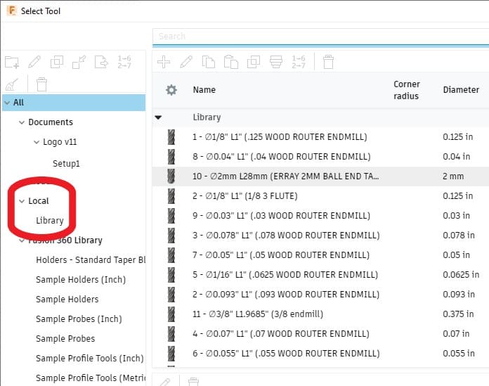
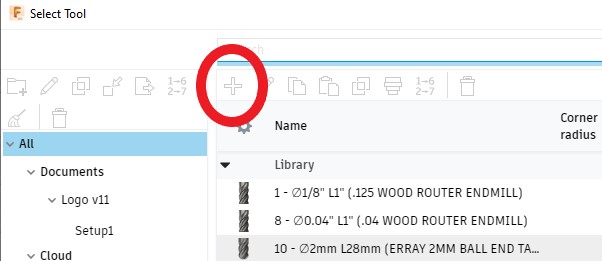
This will open up a blank Library of tools, (I already added a bunch). Click the ‘plus’ symbol at the top to add your first tool. Another window will popup asking you what type of tool to select.
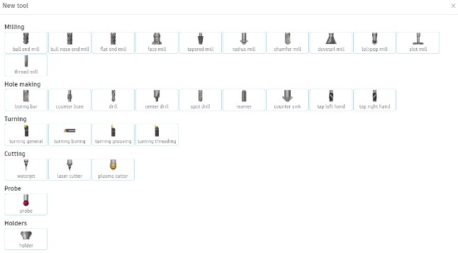
Choose a type of tool and when selected another window will popup which will need information adding about your cutter.
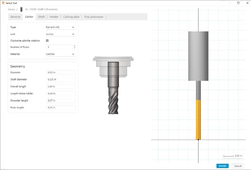
- In the General tab, give your tool a name so you can recognize it in your list of tools.
- In the Cutter tab, fill in the diameter and lengths
- Skip the Shaft and Holder tabs, they are not needed
- In the Cutting Data tab add a spindle speed and feed, any if you are not sure. It can be changed later.
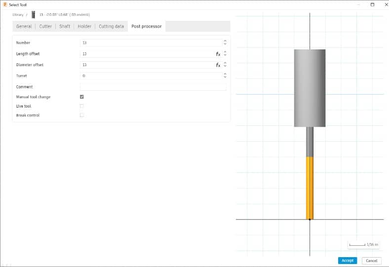
- In the Post Processor tab give your tool a number, use the same number for length and offset.
- If you don’t have a tool changer, check the manual tool change box. Ignore the rest of the boxes.
Click ‘Accept’ and the tool will be added to your library and will be available for selection in the future. You only have to fill all that in once.
Highlight the cutter in your library that you want and press select.
All the information needed in the Feed & Speed section will have been automatically entered using the information you entered when setting up the tool in your library.
This can be changed if you want or need to.
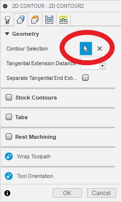
Geometry Tab
For a simple outline tool path, we only need to consider the geometry section of this tab.
Click the contour selection mouse pointer symbol, highlight the outer boundary of your model and select it.
The direction arrow will show the direction of the tool path, you can click it to change the direction.
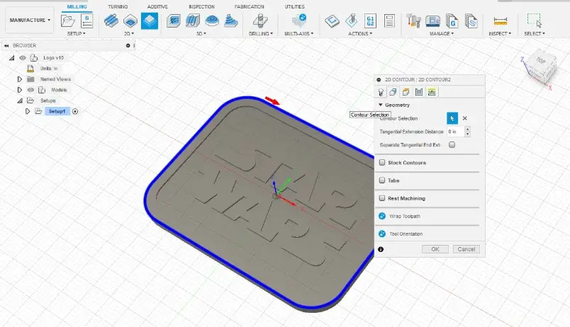
I recommend leaving it as climb milling (as shown in the picture).
Heights Tab
This is self explanatory, fill in the values. I always have the feed height .01” above the top of the part.
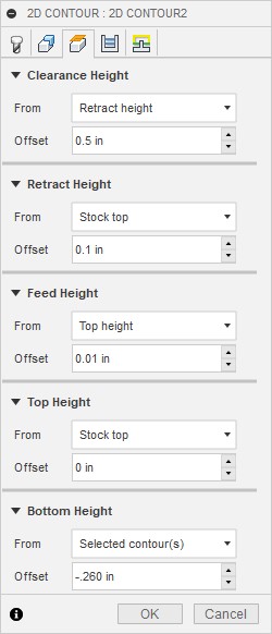
The bottom Height is the distance you want the cutter to go to in the Z axis.
I have set my value to go .01” past the thickness of my stock into my spoil board. This ensures a clean cut bottom edge.
Passes Tab
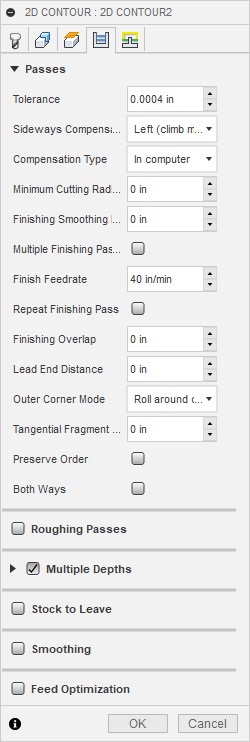
Passes Section
- Tolerance – leave as is
- Sideways Compensation – leave it as ‘Left’ (climb milling)
- Compensation Type – Leave as ‘In Computer’
Multiple Depths Section
- Maximum Roughing Stepdown – Set the depth of cut in the Z Axis for your tool. This will force the tool to do multiple passes down to your final Z depth.
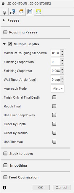
You can leave everything else un-checked in this tab.
Linking Tab
Linking Section
- High Feedrate Mode – leave as is
- Allow Rapid Retract – Just keep it checked
- Safe Distance – You can leave as is, I change mine to .01” (habit)
- Keep Tool Down – Leave this unchecked
- Lift height – Leave as is, This is only needed with certain milling strategies, I change mine to 0” (habit)
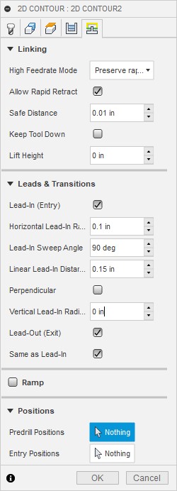
The first ‘Linking’ section of this tab does not need to be over analysed, I usually just change my safe distance to .01”, but you can just leave this area as default.
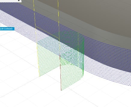
Leads & Transitions Section
The lead in function is used to prevent your end mill plunging against a finished face. I recommend using lead-ins and outs. They are not difficult to set up and help the finish by preventing unsightly gouges on the sides of your finished part.
- Lead-In (Entry) – Keep checked
- Horizontal Lead-In Radius – 0.1”
- Lead-In Sweep Angle – 90 deg
- Linear Lead-In Distance – 0.15”
- Perpendicular – Leave unchecked
- Vertical Lead-In Radius – 0.0”
- Lead-Out (Exit) – Keep Checked
- Same As Lead-In – Keep Checked
Obviously the values I have dictated above suit an outside profile similar to the one I have just done. If your profile is different, just experiment with different values until you have something suitable.
Ramp Section
Just leave ramp un-checked
Positions section
You can ignore this section
Now you can press OK or hit Enter. If you hit enter before you finish or if you need to change anything just double click the ‘contour’ file in the browser tree.
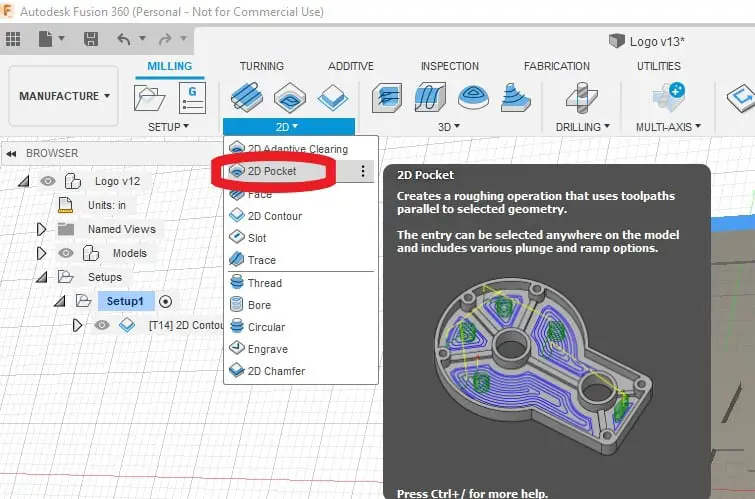
2D Pocket
Now you need to mill all the detail in the center around the lettering. To do this you can use 2D Pocket.
Most of the values in the 2D Pocket popup box are the same as the outside contour I have just gone through, so I will only explain the ones that differ.
Select 2D Pocket from the menu bar.
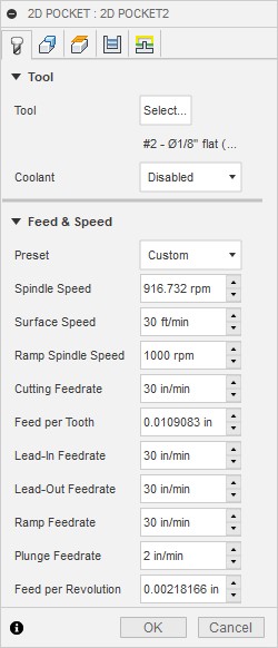
Tool Tab
The change here from the outside contour will be my choice of tool. I will select a smaller endmill to be able to mill more detail. Then I will need to use progressively smaller end mills to get as far into the corners as possible.
My first endmill will be 1/8” diameter. If you need to create a new endmill in your library do it now as explained previously.
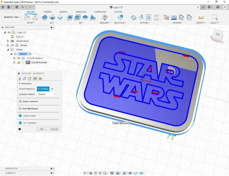
Geometry Tab
- Geometry Section – Here you will have to select all boundaries you want to mill. Select all the flat areas around and in-between the letters.
You will notice that the highlighted areas look a bit odd with my contour selections. Not sure why it did this but it still created the toolpaths correctly.
- Stock Contours – Leave this alone
- Rest Machining – Leave this alone. (This function will be used in the next operation)
Heights Tab
All these values are repeated from the last contour operation apart from ‘Bottom Height’.
Add the depth of your pocket here, use a minus value to specify the direction of travel.
Passes Tab
Passes Section
- Tolerance – Leave as is
- Sideways Compensation – Leave as Left (climb milling)
- Minimum Cutting Radius – Leave as Zero
- Finishing Passes – Leave unchecked
- Preserve Order – Leave unchecked
- Both Ways – Leave unchecked
- Maximum Stepover – This dictates how far over your end mill will move for each pass. I typically make mine a little over the size of the cutter radius.
Multiple Depths Section
- Maximum Roughing Stepdown – set your maximum depths of cut here. You can leave the rest of the options in this section as is or unchecked.,
You can leave the rest of this tab as is or unchecked.
Linking Tab
Fill in this tab the same as the first 2D contour except maybe make your Linear Lead-In distance smaller.
Ramp
This section is mandatory in the 2D Pocket contour. It specifies how your cutter will plunge into the material. In this instance it will helix down, this applies less pressure on the Z axis and tool than straight down plunging.
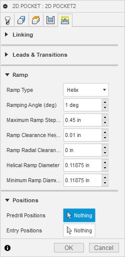
- Ramp Type – Select ‘Helix’, this option usually returns the best result
- Ramping Angle – Choose a low value like 1 degree
- Maximum Ramp Stepdown -Leave as is
- Ramp Clearance Height – Change this to .01”, it helps to keep this small to avoid ‘cutting air’
- Ramp Radial Clearance – Leave as zero
- Helical Ramp Diameter – The smaller you set this the more room the cutter has to do its helical ramp down. If it does not have room it will just plunge, which isn’t ideal.
- Minimum Ramp Diameter – The smaller you set this the more room the cutter has to do its helical ramp down. If it does not have room it will just plunge, which isn’t ideal.
2D Pocket (2nd Toolpath)
Now you have done the first pass, you will notice that the tool was too big to finish all the detail in the lettering. The process needs to be repeated using a smaller diameter end mill.
There is a quick and easy way to do this using the ‘Rest machining’ function.
But first you need to create another 2D Pocket toolpath by duplicating the one you just completed.
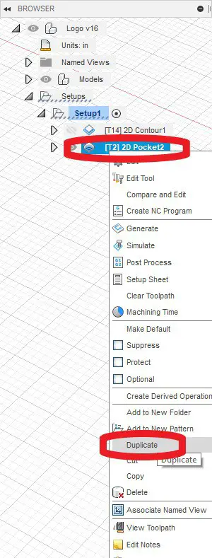
Rest Machining
- Right click your ‘2D Pocket’ Toolpath in the browser tree.
- Click ‘duplicate’ in the popup menu
- Double click your new ‘2D Pocket’ Toolpath to edit it.
- In the Tool Tab select a smaller End mill, I used a 1/16″ for this second pocket toolpath
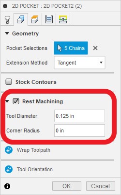
- In the Geometry Tab, check ‘Rest Machining’
- Enter your previous end mill diameter in the Tool Diameter box
- Click OK
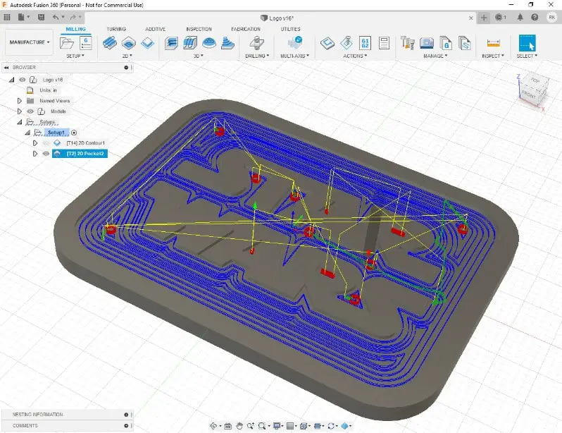
As you can see from the picture of the new toolpaths it will only mill in the areas that the previous cutter was unable to reach.
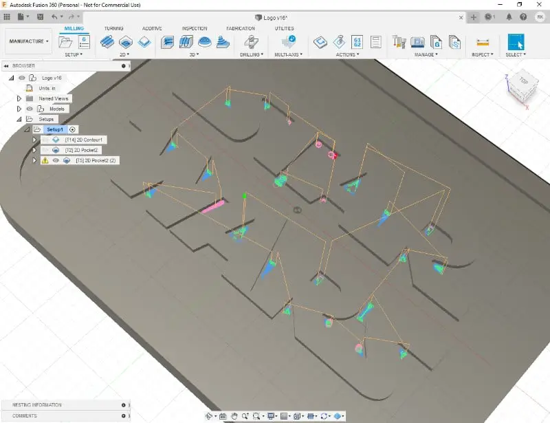
There is one area between the ‘W’ and the ‘A’ that it was unable to fit the tool into.
This means we have to repeat the process with an even smaller cutter. I used a .03″ diameter cutter for this.
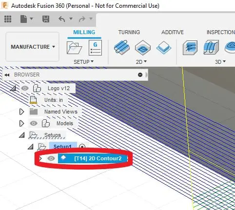
Once this is done there will be 4 tool paths in the browser tree ready to be simulated and post processed.
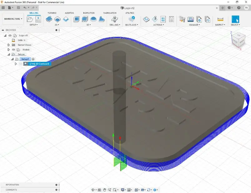
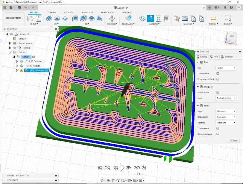
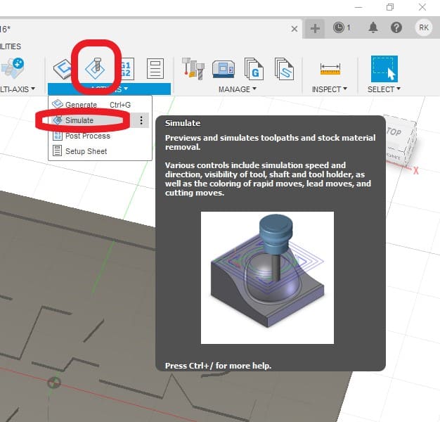
Simulate
Simulate enables you to check exactly what your toopaths are going to create.
- Select each or all of your toolpaths in your browser tree. To select all, click the first then hold the shift key and select the last one. The ones you want to simulate should be highlighted in blue.
- Click the Simulate button
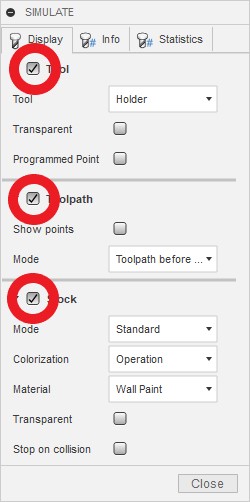
- Use the Display Tab to select Tool, Toolpath and Stock
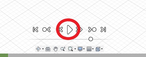
- Press the ‘Play’ button at the bottom of the screen
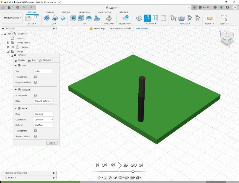
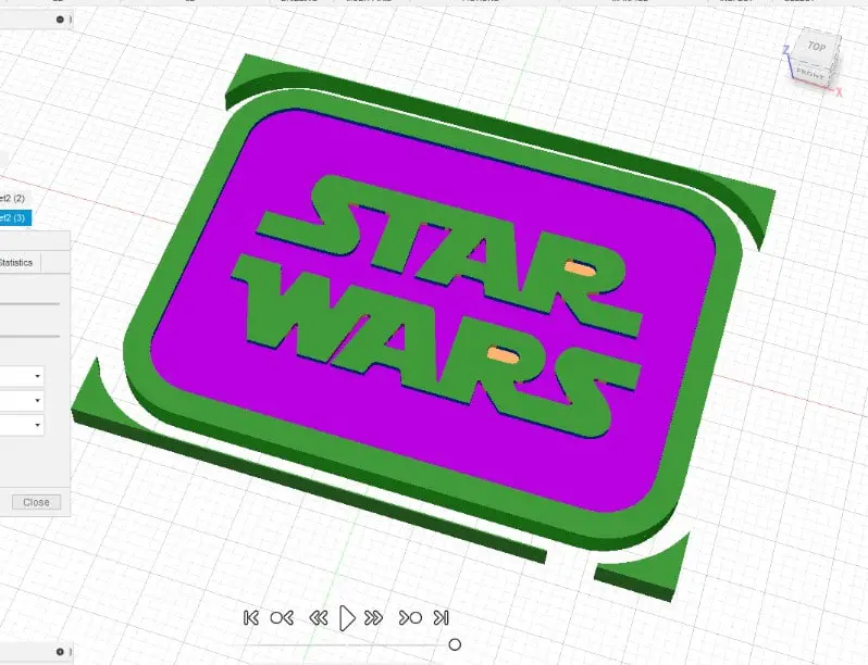
You can switch off ‘tool’ and ‘toolpath’ to get a clearer view of the finished simulation.
Post Process
Post processing your toolpaths with a free subscription can only be done with individual toolpaths selected from the browser tree.
- Highlight the first toolpath in the browser tree
- Click the post process button
- Select the output (destination) folder on your PC
- Select your post processor file, e.g. GRBL
- Give your file a name
- Click ‘Post’
- Your file should now open up in a text editor
- Repeat for each toolpath in the browser tree
You will now have a bunch of G Code programs you can run on your machine to create your project.
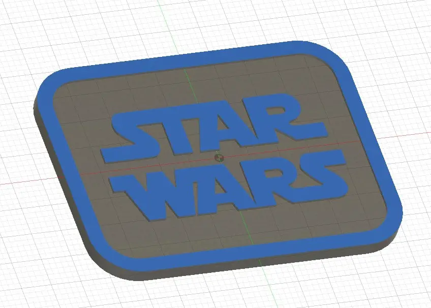
If you want to use my Star Wars SVG file you can download it below.